As we all know that Time plays an important role for most of the sequential functions in industrial, domestic as well as commercial applications.
PLC timer instructions can give freedom from mechanical and electromagnetic timer relay from hard wiring.
In this blog, we are going to see a brief overview of PLC timer instructions with practical examples.
Let’s start the blog.
Table of Contents
PLC Timer Instructions
Timer plays a significant role to control the operation for a specific period of time. As a very basic example, we require a timer to control the transition from star to delta function in a star-delta electrical motor starter.
There are lots of applications where timers are used in PLC programming.
Electromagnetic Time-Delay Relay vs PLC Timer Function
In a conventional control relay system, contact is changed as soon as voltage is applied to the coil. While in a time-delay relay, contact is changed after a preset time when the voltage is applied to the coil.
Time-Delay relays are very easy to use. You just have to apply the voltage to the coil and wait for a preset time to change the contact.
This is the block diagram of Time-Delay Relay:

There are different types of Time-Delay relays available in the market:
- On-delay timer
- Off-delay timer
- On/Off delay timer
On-Delay Timer Relay
In an On-Delay timer timing begins when the voltage is applied to the coil of the timer. The contact changes as soon as time has expired and remains changed until the voltage is removed from the coil.
Off-Delay Timer Relay
In an Off-Delay timer when the voltage is applied to the coil nothing happens. When the input/trigger switch closes, output contact changes and timing begins. The output contact remains changed until the timing is finished or voltage is removed from the coil.
On/Off Delay Timer Relay
In an On/Off delay timer, we have the functionalities of both an on-delay timer and an off-delay timer. There is a functionality of a repeat-cycle also on this type of time delay relay.

Advantages of PLC Timer over Electromagnetic Time-Delay Relays
- Time Value and Timer function can be changed very easily by just changing a program without any hardware changes.
- No maintenance is required in the PLC timer.
- We can use as many contacts of the PLC timer in the program, No additional standard control relay is required to further extend the logic.
- Users can easily implement the logic using the PLC timer as required.
In PLC we have different instructions for timer functions like,
In Siemens PLC,
- S_PULSE (Pulse Timer)
- S_PEXT (Pulse-Extended Timer)
- S_ODT (On-Delay Timer)
- S_ODTS (Retentive On-Delay Timer)
- S_OFFDT (Off-Delay Timer)
In Allen Bradly PLC,
- TON (On-Delay Timer)
- TOF (Off-Delay Timer)
- RTO (Retentive On-Delay Timer)
The addressing is different for different brands of PLC, but the logical operation and functions are very similar.
Siemens PLC Timer Block
These are the blocks used as a timer in Siemens PLC ladder logic.

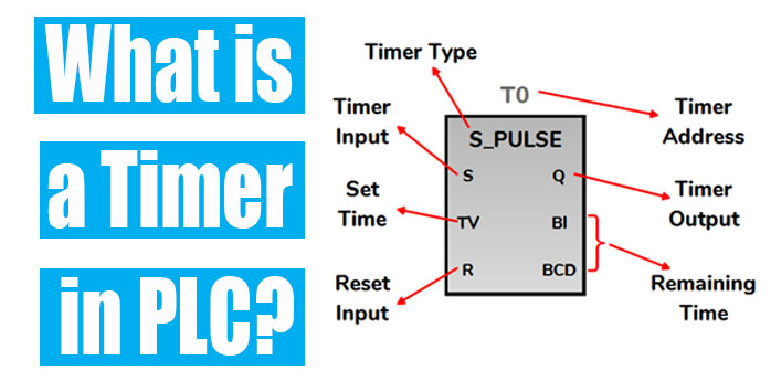
Each timer block has bits like S, R, Q and words like TV, BI, and BCD.
S ⇒ Set bit to trigger the timer block
R ⇒ Reset bit to reset the timer block.
Q ⇒ Status bit of a Timer block.
TV ⇒ Preset Time Value of Timer block.
BI ⇒ Remaining Time Value in an Integer format.
BCD ⇒ Remaining Time Value in BCD format.
S_PULSE (Pulse Timer)
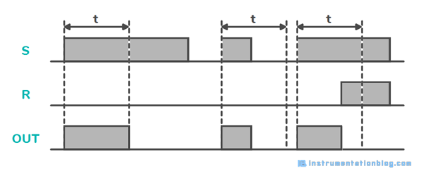
This timer starts when there is a positive change from 0 to 1 at the set bit(S).
The timer runs for the preset time as long as the signal at the set bit is 1. When the timer is running and the signal at the set bit(S) changes from 1 to 0, the timer will be stopped and the status at the output will be 0.
A timer is reset when there is a change from 0 to 1 at the Reset bit(R) while the timer is running. The remaining value also sets to 0 in both BI and BCD.
A positive change at the set bit(S) is always necessary to activate the timer again.
S_PEXT (Pulse Extended Timer)
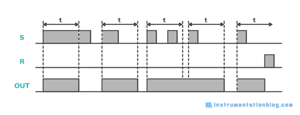
This timer starts running when there is a positive change from 0 to 1 at the set bit(S).
The timer runs for the preset time even if the signal state at the set bit(S) changes to 0 before the preset time is elapsed.
The status of the timer block is 1 as long as the timer is running. A positive change at the set bit(S) is always necessary to activate the timer again.
A timer is reset when there is a change from 0 to 1 at the Reset bit(R) while the timer is running. The remaining value also sets to 0 in both BI and BCD.
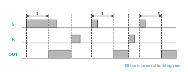
S_ODT (On-Delay Timer)
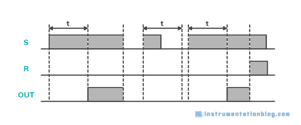
The ODT timer starts running when there is a positive change from 0 to 1 at the set bit(S). A positive change is always necessary to start the timer again.
The timer runs for the preset time value(TV) as long as the signal at the set bit(S) is 1. The status bit(Q) is 1 after the timer has completed its preset time without any error until the signal state of set bit(S) is positive.
When the signal at the set bit(S) changes from 1 to 0 while the timer is running or stopped, in this case, the status at the output will be 0.
A timer is reset when there is a change from 0 to 1 at the Reset bit(R) while the timer is running. The remaining value also sets to 0 in both BI and BCD.
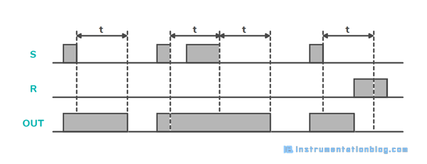
S_ODTS (Retentive On-Delay Timer)
The ODTS timer starts running when there is a positive change from 0 to 1 at the set bit(S). The timer runs for the preset time value(TV) even if the signal state at the set bit(S) changes to 0 before the preset time value(TV) is completed.
The status bit(Q) is 1 after the timer has completed its preset time without regard to the signal state at the set bit(S). The timer will be re-triggered with the preset time value(TV) when there is a change at the set bit(S) while the timer is running.
A timer is reset when there is a change from 0 to 1 at the Reset bit(R) while the timer is running. The remaining value also sets to 0 in both BI and BCD.
S_OFFDT (Off-Delay Timer)
The OFFDT timer block starts running when there is a negative edge at the set bit(S). A signal change at the set bit(S) is always necessary to start the timer again.
The status bit(Q) is 1 as soon as the signal state at the set bit(S) is positive and while the timer is running.
The timer is reset when the signal state at the set bit(S) goes from 1 to 0 while the timer is running. A timer is reset when there is a change from 0 to 1 at the Reset bit(R) while the timer is running. The remaining value also sets to 0 in both BI and BCD.
Allen Bradley PLC Timer Block
These are the blocks uses as a Timer block in Allen Bradley PLC.
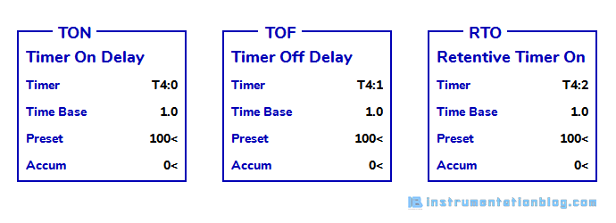
Each timer block has EN, DN, and TT bits.
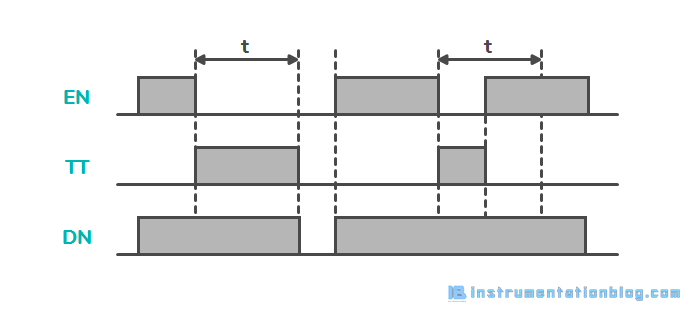
TON (Timer On Delay)
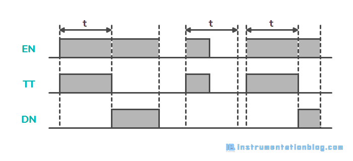
The TON timer starts running as soon as it gets a positive state of a signal at the input.
The status of the Enable(EN) bit is 1 when the rung conditions are true. The Timer Timing(TT) bit is set while the timer is running.
The status at the Done(DN) bit is high when the timer has completed its preset time without any error and will be high until the supply at the timer is high.
TOF (Timer OFF Delay)
The TOF timer starts running when there is a negative edge at the timer input signal. It starts counting when the Enable(EN) bit is OFF and stops when the accumulated value is reached or when the Enable(EN) bit is ON.
The Enable(EN) and Done(DN) bits work the same as the TON timer block. The Timer Timing(TT) bit is set while the timer is running.
RTO (Retentive Timer On Delay)
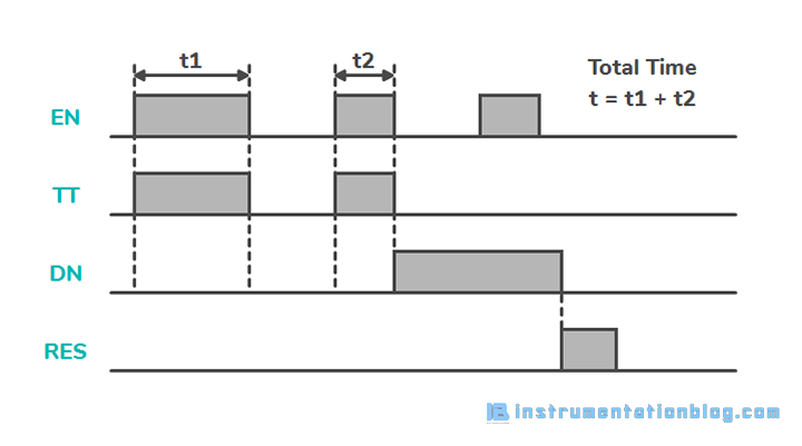
RTO is the retentive on-delay timer in the Allen Bradley plc system. RTO instruction is the same as the TON and TOF, except for the fact the accumulated value is retained even if the rung conditions go false.
The Enable(EN) bit is ON when the rung conditions are true. The Timer Timing(TT) bit is ON when the rung conditions are true and the accumulated value is less than the preset value. The Done(DN) bit is ON after the timer has completed the preset value without any error.
The RES instruction must be used to reset the RTO timer and to start the timer again.
PLC Timer Examples
There are tons of examples in which PLC timer instructions are used. Out of all these, I am giving you examples of some most useful logic like,
- Traffic Control Signal
- Zero Speed Sensor detection
- Equipment Running Status Interlock
- Closed-loop Control
- Equipment Tripping Command
- Hourly and Daily Data Logging
- To Calculate the Rate of Flow
- PID Control
- Calculate Motor Running Hours
Summary(PLC Timer Instructions)
This is all about the PLC timer block. I hope you are clear now about What are Timers in PLC? Types of Timers in PLC. How does a timer work in a PLC system?
If you really like this blog and you want more PLC tutorials like this then you can comment down below.
Next Must-Read Articles:
⇒ What is PLC? How does it work?
⇒ Sinking and Sourcing Circuits.
⇒ Logic Gates using PLC Ladder logic.
⇒ 5 different types of PLC programming languages.
⇒ Electrical motor starter with a PLC program.
⇒ 20+ Arithmetic instructions in PLC Programming.
⇒ Types of PLC Counter in PLC Programming.
⇒ Different Types of Siemens PLC Programming blocks.
⇒ 30+ Most useful PLC Communication Protocols.
⇒ Converter instructions in PLC Programming.
⇒ Analog Scaling and Unscaling in PLC Programming.
⇒ Difference between FC and FB in Siemens PLC.