Table of Contents
What is Scaling and Unscaling in PLC?
We have seen in my previous articles that What is PLC? and How does it work? In this article, we have seen PLC Architecture, Types of PLC, Advantages, and Disadvantages of PLC, Applications of PLC.
There are multiple sensors we can find in the industries. The output of these sensors is either digital or analog. We have also seen in my previous article about What are Digital and Analog Input-outputs?
Digital Input-Output has only two states: It can be either ON or OFF.
Analog Input-Output has multiple states: It can be 0%, 5%, 50%, 90%, 100% etc.
In this article, we will be seeing about Analog Input-Outputs. How this analog input-output is connected with PLC? What is Scaling and Unscaling in PLC in terms of analog input-output?
So, Let’s dive into this.
Analog Input Scaling Scenario
Every analog input module has some resolution like the PLC Analog module accepts 16 bits of data. It means it has a range of 2^0 = 0 to 2^15 = 32768. But PLC has defined standard limits in terms of under range, rated range, over-range.
So values less than 4 mA are considered as under range values. Values between 4 to 20 mA are considered as a standard range and values beyond 20 mA are considered as over-range values.
In Siemens 300/400 series plc, there is a scaling block(FC105) that can be used for this conversion.
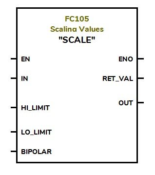
FC105 takes this integer value of 0 – 27648 as an input in IN and converts it into real values in the given range. The lower value of the range is given into LO-LIMIT and a high value of the range is given into HI-LIMIT.
There is also another input for the Unipolar or Bipolar selection. The input integer range is assumed 0 to 27648 for the unipolar selection and -27648 to 27648 for bipolar selection.
OUT gives us converted real value. RET_VAL gives a return value, such as it gives W#16#0000 if the instruction executes without error.
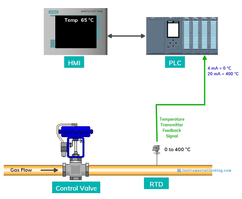
Let’s take a scenario, there is an RTD-temperature transmitter installed at the top of the furnace. The RTD has a transmitter that converts the 0 ºC to 400 ºC into a 4 – 20 mA electrical signal.
Now, we have to convert the 4 – 20 mA electrical signal into a 0 – 400 engineering value. So that we can use it for display or further calculation. PLC AI module understands 4 mA as a 0 integer value and 20 mA as a 27648 integer value.
Analog Output Scaling Scenario
Same as the Analog input module, the Analog output module has the same range. Let’s take another example of giving input of the speed to the VFD.
We have a variable frequency drive, an induction motor is driven from this drive. The induction motor has a nameplate speed of 1440 rpm. The speed input for the motor is given from the PLC to the VFD. We are using HMI to vary the speed.
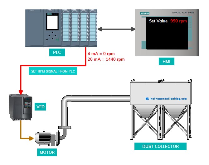
There is an unscaling block FC106 in the Siemens PLC system, that converts the engineering unit of 0 to 1440 rpm into an integer value of 0 to 27648. Here integer 0 value represents a 4 mA to the drive and 27648 integer value represents a 20 mA to the drive.
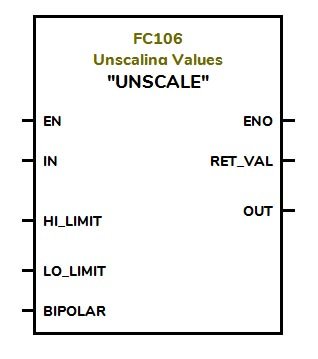
FC106 takes the real value of 0 – 1440 as an input in IN and converts it into integer values in the given range. The lower value of the range is given into LO-LIMIT and a high value of the range is given into HI-LIMIT.
There is also another input for the Unipolar or Bipolar selection. The output integer value is assumed 0 to 27648 for the unipolar selection and -27648 to 27648 for bipolar selection.
OUT gives us converted integer value. RET_VAL gives a return value, such as it gives W#16#0000 if the instruction executes without error.
Analog Input-Output Scaling
Let’s take an example of a control valve. A control valve has both analog input and analog output.
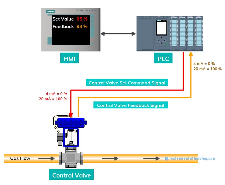
A control valve accepts 4-20 mA from the PLC as the input command to open and provides an output of 4-20 mA to the PLC as the feedback signal of valve position.
It means when the operator gives a command to open the valve at 0%, the PLC sends an electrical signal of 4 mA to the valve. And for the 50%, PLC sends an electrical signal of 12 mA to the valve, and for the 100%, PLC sends 20 mA.
FC106, unscaling block, converts the real value of 0% to 100% into 0 to 27648 integer value and provides an analog output signal of 4-20 mA to the valve.
The control valve also provides an output signal to the PLC to indicate the current position of the valve. When the valve is 0% open, it sends 4 mA to the PLC, for the 50% it sends 12 mA and for the 100%, it sends 20 mA to the PLC.
FC105, scaling block, converts the 0 to 27648 integer value into a real value of 0% to 100% and displayed it on the HMI.
Summary
I hope you like this blog about scaling and unscaling in plc. You must like the below-mentioned PLC programming-related articles.
⇒ Basics of bit logic instructions.
⇒ Most popular PLC programming languages.
⇒ Arithmetic instructions in PLC programming.
⇒ Basics of PLC Timer instructions.
⇒ Basics of PLC Counter instructions.
⇒ Siemens PLC programming blocks.
⇒ Most used PLC communication protocols.
⇒ Most important PLC interview questions.
You can read more articles about Instrumentations and find books that boost your knowledge in the field of instrumentation ⇒
Thanks for reading!