Table of Contents
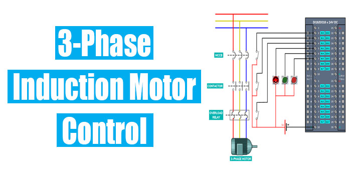
Three Phase Induction Motor Control using PLC
In this tutorial, you will find the basic steps about how to control a three-phase induction motor using a programmable logic controller?
Before going to this tutorial I would like to refer to What is a programmable logic controller? and What is an Induction Motor?
Step#1: Decide the inputs and outputs.
Inputs
- Safety Switch
- Start Pushbutton Switch
- Stop Pushbutton Switch
- MCCB feedback
- Contactor feedback
- Overload relay feedback
Outputs
- Contactor Coil which drives an induction motor
Step#2: Decide the PLC
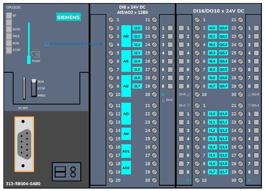
We will take a Siemens S7-300 series PLC, model no. S7 314C.
Step#3: Prepare power and control drawings.
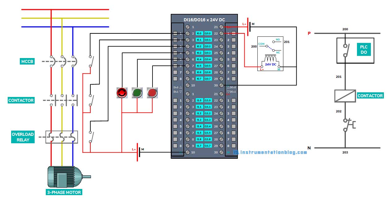
There are MCCB, Contactor, and Overload Relay in the power drawing. We have used the feedback as NO contact from MCCB, Contactor, and Overload Relay and connected it to inputs I0.0, I0.1, and I0.2.
There is a safety switch, start pushbutton, and stop pushbutton which is connected to I0.3, I0.4, and I0.5.
The output Q0.0 is driven to a 24V DC relay and the relay’s NO contact will be used as the main driver to conduct a contactor coil in the control.
Step#4: Prepare a PLC program
Network#1: This network is showing the ready status of the motor, if the MCCB is ON and the safety switch is in a normal position then the motor is ready to start.
Network#2: This network shows the start logic for the motor. If there is no error and the motor is ready to start then when the operator presses the start button from the local panel it will activate the driver to start the motor.
Network#3: Whenever the operator presses the stop pushbutton it will deactivate the driver.
Network#4: This network stops the driver in the case of contactor malfunction.
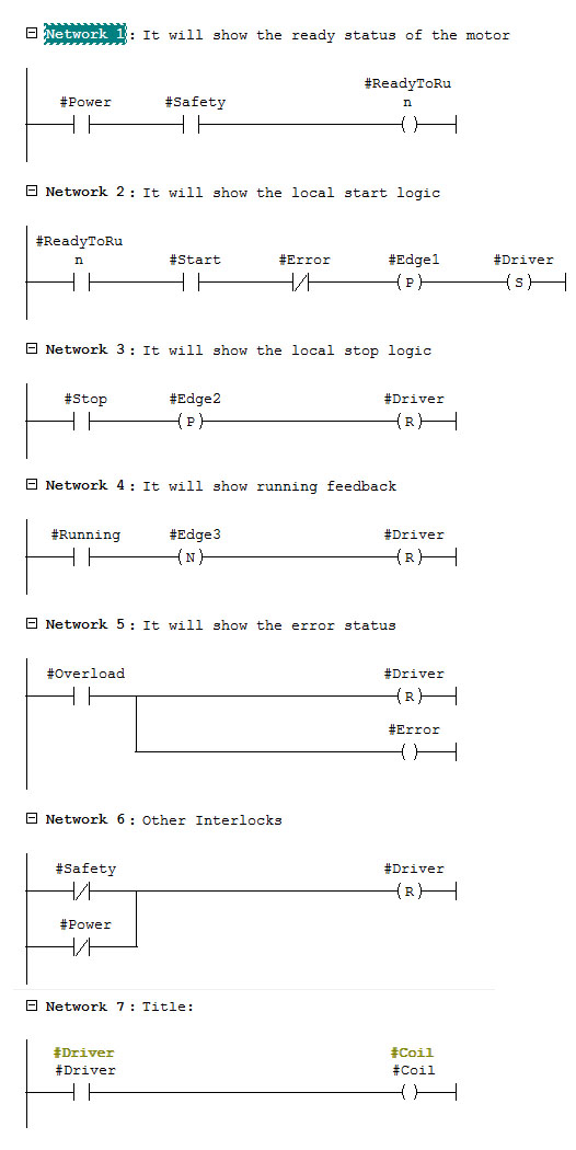
Network#5: This network shows the error status or trip status of the motor due to excessive current from the overload relay.
Network#6: Whenever the operator presses the safety switch or power MCCB goes off then it will deactivate the driver in this network.
Network#7: The status of the driver is transferred to the coil which is the main output of the PLC.
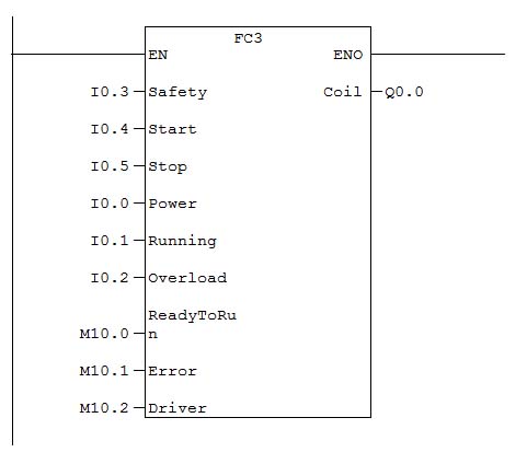
This is the function block of the three-phase induction motor control.
Note: This is the basic tutorial about the 3 phase induction motor control using PLC. However, the practical application may be somewhat different.
Next Must-Read Articles,
- Basics of bit logic instructions.
- Most popular PLC programming languages.
- Arithmetic instructions in PLC programming.
- Basics of PLC Timer instructions.
- Basics of PLC Counter instructions.
- Siemens PLC programming blocks.
- How to interface a PLC system with SCADA or HMI?
- How to read real-time clock values in a PLC system?
- Most used PLC communication protocols.
- Most important PLC interview questions.
You can read more articles about Electrical and you can also find books that boost your knowledge in the field of Instrumentation ⇒
Thanks for reading!
