Table of Contents
Basics of AC Motors | Induction Motors
AC Motors are used worldwide in many residential, commercial, industrial, and utility applications. An AC motor may be a part of a pump, blower, conveyor, or mixer.
Motors transform electrical energy into mechanical energy.
AC motors are mainly classified into two categories: Synchronous Motor and Asynchronous Motor.
Synchronous Motor
Synchronous Motor converts alternating current and converts into mechanical power. It operates at a synchronous speed. The speed of the rotating magnetic field is referred to as a synchronous speed(Ns).
Below is the simple formula to find out the synchronous speed,
Ns = (120F/P), where F=frequency and N=Number of Poles
As an example, the synchronous speed for a two-pole motor operated at a frequency of 50Hz is 3000 rpm.
The synchronous speed decreases as the number of poles increases.
| Number of Poles | Synchronous Speed |
| 2 | 3000 |
| 4 | 1500 |
| 6 | 1000 |
| 8 | 750 |
| 10 | 600 |
Asynchronous Motor
An asynchronous motor is commonly referred to as an AC induction Motor. An induction motor converts an alternating current into mechanical power at a speed less than the synchronous speed, that is why it is known as an asynchronous motor.
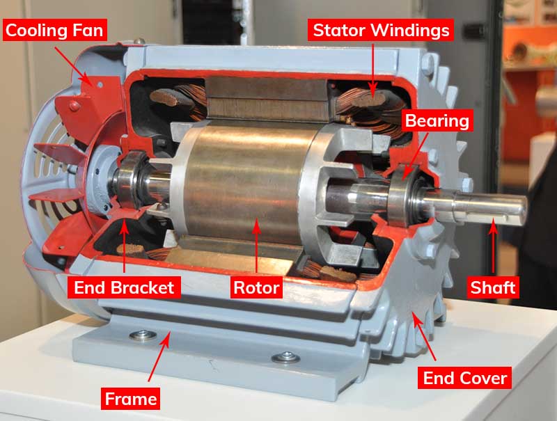
image reference from Wikipedia
AC induction motors are commonly used in industrial applications. The important parts of the induction motor are as below:
⇒ Stator
⇒ Rotor
⇒ Bearings
⇒ End Bracket
⇒ Cooling Fan
Stator
The stator is the stationary electrical part of the induction motor. The stator is made up of high-grade alloy steel thin laminations to reduce eddy-current losses.
The stator has mainly three parts: Outer Frame, Stator Core, and Stator Windings.
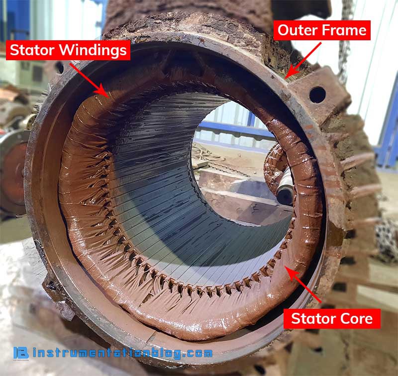
The outer frame is the outer body of the motor that houses the stator core and protects the inner parts of the induction motor. It is generally of casting from small motors and fabricated for large motors.
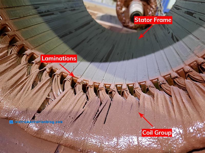
The stator core is made up of several hundred high-grade silicon steel thin laminations. Stator laminations are fixed together into slots in the stator frame. Coils of insulated wire are inserted into slots of the stator core.
Each lamination is insulated from the other through the thin varnish layers. Each grouping of coils, together with the steel core it surrounds forms an electromagnet.
The stator windings are directly connected with the three-phase power source. There are six terminals (two of each phase) are connected in the terminal box of the induction motor.
There is a definite number of poles of the stator windings. If the number of poles increases then the speed of the motor decreases and if the number of poles decreases then the speed of the motor increases.
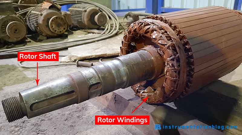
Rotor
The rotor is the rotating electrical part of the induction motor. There are mainly two types of rotors: Squirrel Cage Rotor and Phase Wound Rotor.
Squirrel-Cage Rotor
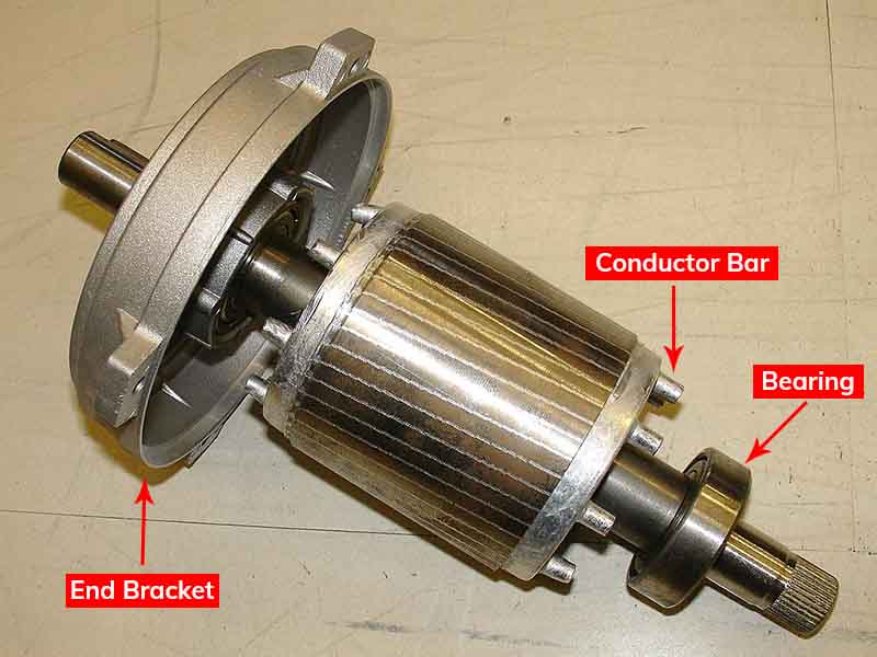
A squirrel-cage rotor consists of a stack of steel laminations with evenly spaced conductor bars around the circumference. The conductor bars are made up of aluminum or copper, which are connected with the end rings.
Current flows through this conductor bar to form an electromagnet. The rotor slots are usually skewed, not parallel to the shaft. This reduces the humming noise of the motor as well as provide uniform torque.
Phase-Wound Rotor
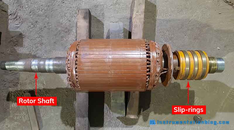
The construction of a phase wound rotor is different from a squirrel-cage rotor. A phase wound rotor is also called a slip-ring rotor. It has a cylindrical laminated core. It has a semi-closed slot on the outer periphery which carries a 3-phase insulated winding.
The slip-ring rotor windings are connected in a star. The slip-rings are mounted on a shaft as shown in the diagram. There are brushes on the slip-rings. The brushes are connected with variable resistance. It adds an external resistor to the rotor circuit.
The main function of the slip-ring is to increase a starting torque and to reduce the starting current. It also controls the initial speed of the motor.
End Bracket
End Brackets are known as bearing housings. Bearings are mounted on the end brackets. There are two end brackets fitted on each side of the motor frame.
The end brackets support the rotor in a way that there is a slight air gap between the stator and the rotor. There is no direct physical connection between the stator and the rotor.
Bearings
Bearings are mounted on the shaft which is then installed on the end brackets. The purpose of bearings in an electric motor is to give support the rotor and to maintain the air gap small and consistent.
Cooling Fan
A cooling fan is usually installed on the opposite end of the output shaft. The cooling fan rotates with the motor. The purpose of a cooling fan is to provide increased airflow to the motors while rotating.
Next Must-Read Articles
⇒ The most used 3 Basic Motor Starter with its PLC Program!
⇒ What is Temperature Scanner? How does it work?
⇒ What is the Servo Motor? How does it work?
⇒ How star-delta starter works?
⇒ What is Soft Starter? How it works?
⇒ Circuit Breaker Fundamentals.
⇒ Relay Working and its importance in an electrical field.
You can read more articles about Electrical and you can also find books that boost your knowledge in the field of Instrumentation ⇒
Thanks for reading!