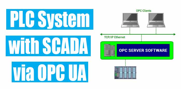
Connection of PLC System with SCADA via OPC UA
You have heard many times about the OPC UA server. In this article, we are going to see how to establish a connection between a PLC system and SCADA via OPC UA.
We are going to use Siemens PLC S7-1500 as a PLC system and WinCC as a SCADA software.
What is OPC?
OPC is a client-server-based communication. OPC client is a software program that is installed on a computer in which SCADA is installed or which is directly connected with the process hardware like HMI.
OPC clients use the OPC server to collect data from the process control hardware devices.
OPC UA (OPC Unified Architecture)
OPC Unified Architecture (OPC UA) is a vendor-independent communication protocol for industrial automation applications.
⇒ OPC UA is platform-independent and features a built-in mechanism. It is flexible and completely independent, So it is regarded as an ideal communication protocol for the implementation of industry 4.0.
⇒ OPC UA is the successor of previous OPC standards generally known as an OPC Classic. OPC Classic has a disadvantage in that it is based on the Microsoft technologies COM and DCOM and therefore it is limited to Microsoft Windows operating systems and networks.
⇒ The standard OPC UA consists of individual specifications. OPC servers and clients do not have to support all the specifications. It is important to consider the particular specifications while implementing the OPC server.
Steps to establishing a connection between PLC system with SCADA:
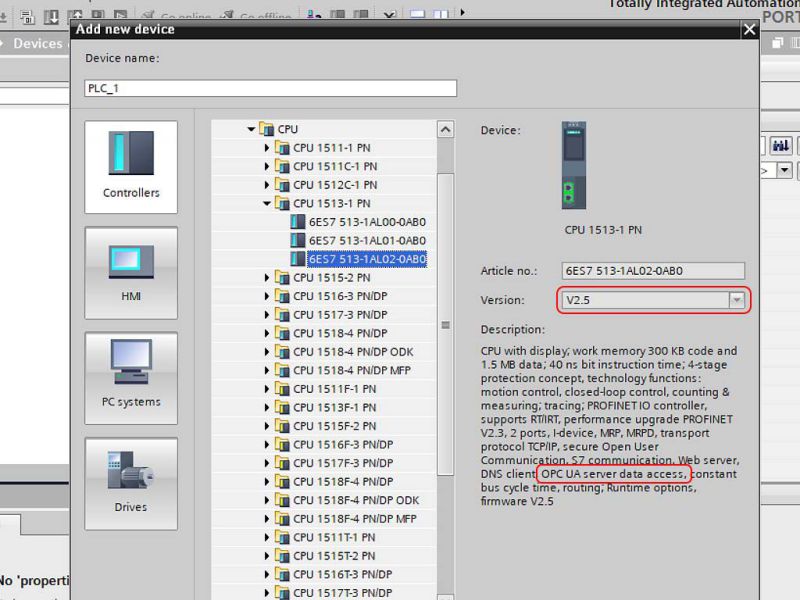
1) Create a New Project in TIA Portal. Select the PLC system with firmware version above v2.5 and which provides OPC UA server data access.
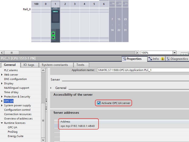
2) Activate OPC Server in the PLC System.
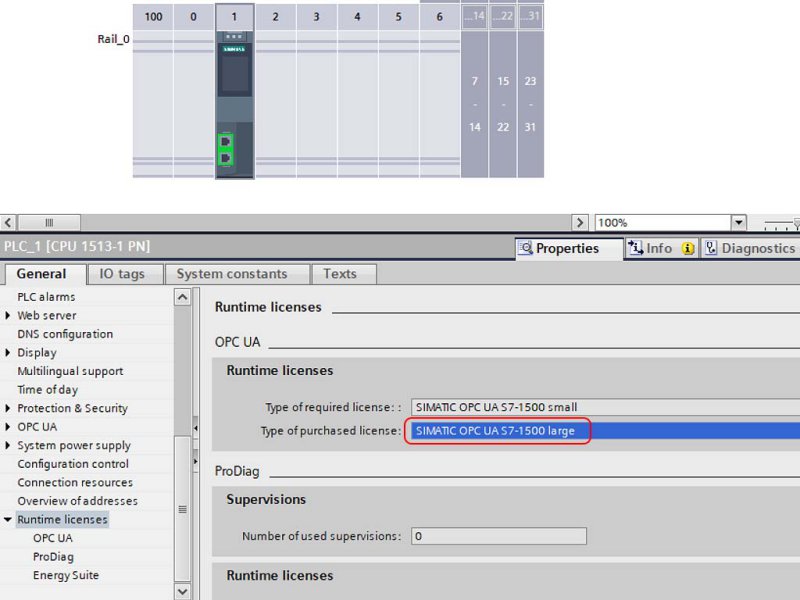
3) Select Runtime License as shown in the below figure.
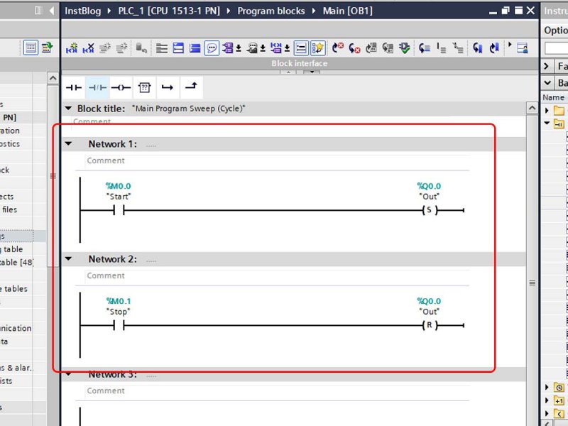
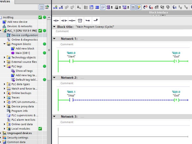
4) Prepare a sample ladder program to check the OPC connection.
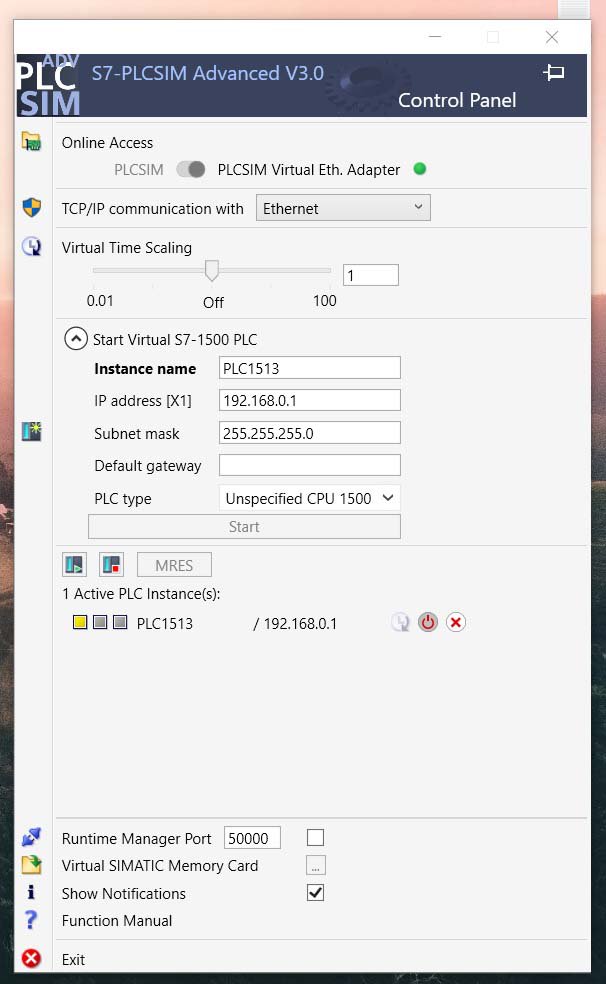
5) Open PLCSIM Advanced and create an instance with PLCSIM Virtual Ethernet Adapter as a normal PLCSIM does not provide the simulation for the OPC UA server.
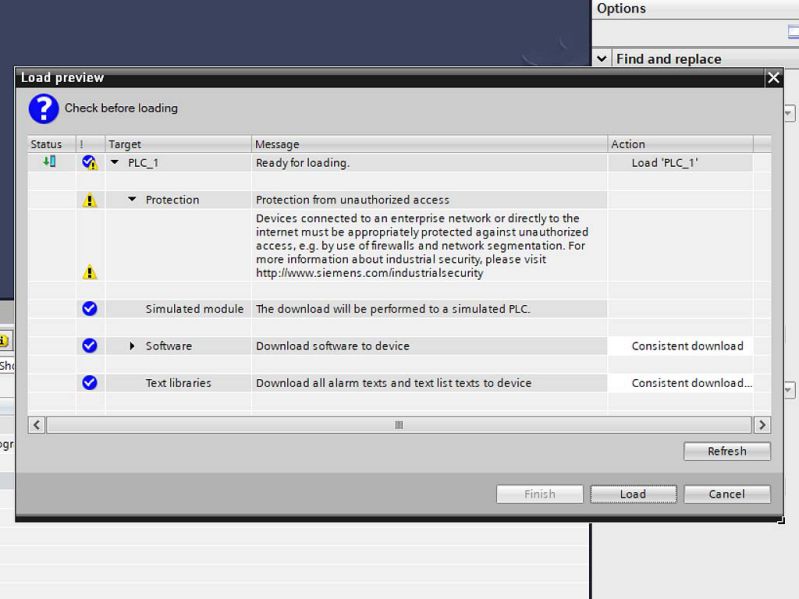
6) Download the user program into the PLC system.
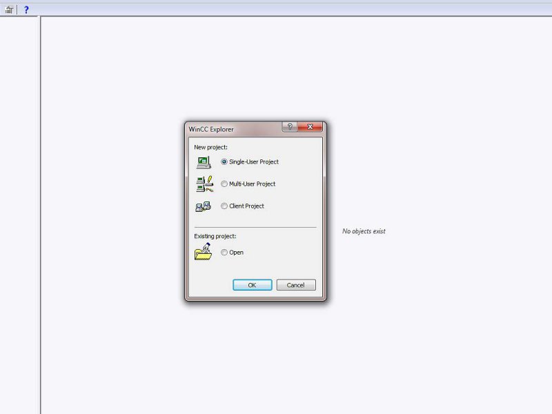
7) Create a new project in WinCC.
8) Add a driver into Tag Management as OPC UA WinCC Channel.
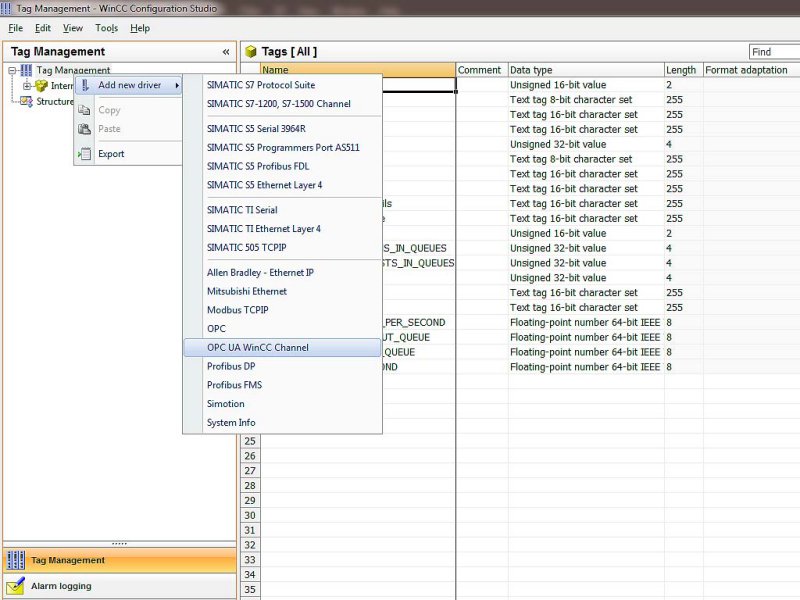
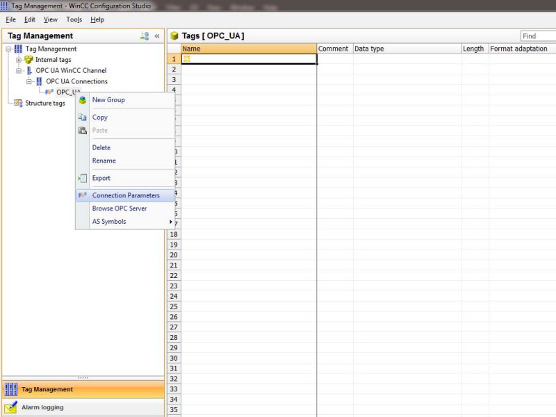
9) Define a connection parameter for the OPC UA Connections.
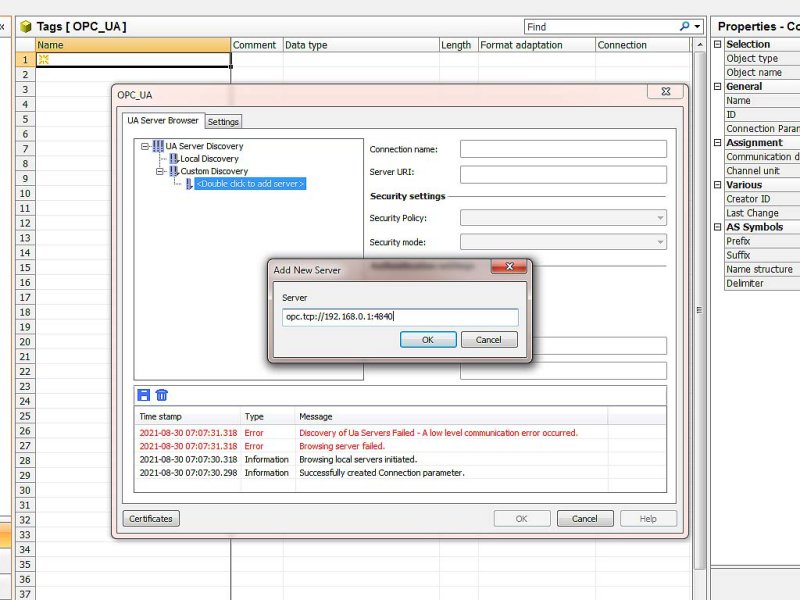
10) Add a server address that we have already assigned in the PLC system.
11) Select security policy and mode as per the given in the PLC system.
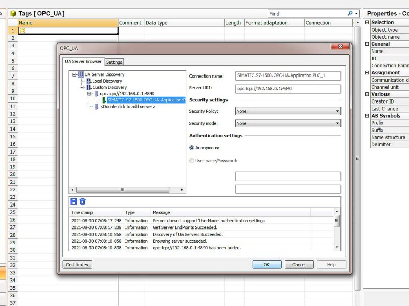
12) Browse OPC Server.
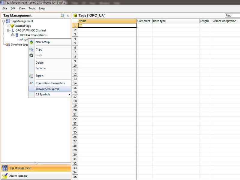
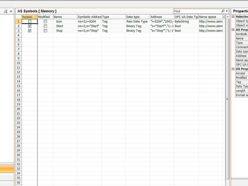
13) Select the input, output, and memory tags from the server.
14) Prepare a graphic to on and off the motor in the Graphics Manager and give all the properties and actions as per the requirement.
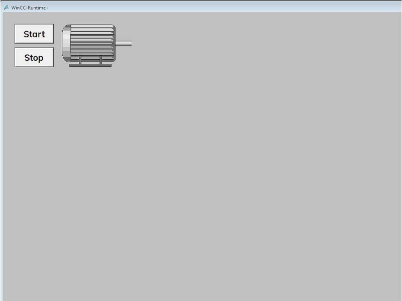
15) When we press the start button it will start the motor as per the user program.
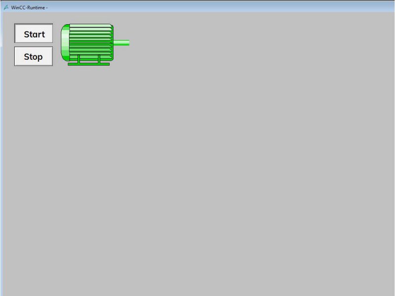
16) We can monitor the user program status in the TIA portal as well.
So, that’s it. Now you got the complete idea about how to communicate a PLC system with SCADA via OPC UA?. If you like this article then give your feedback in the comment section below. Every comment matters for us and gives us the motivation to present more articles like this.
Next Must-Read Articles,
- Basics of bit logic instructions.
- Most popular PLC programming languages.
- Arithmetic instructions in PLC programming.
- Basics of PLC Timer instructions.
- Basics of PLC Counter instructions.
- Siemens PLC programming blocks.
- How to interface a PLC system with SCADA or HMI?
- How to read real-time clock values in a PLC system?
- Most used PLC communication protocols.
- Most important PLC interview questions.
You can read more articles about Electrical and you can also find books that boost your knowledge in the field of Instrumentation ⇒
Thanks for reading!
