Variable Frequency Drive (VFD) is used in many industrial applications to control the speed of the connected electrical motor.
The VFD consists of mainly four sections:
- AC to DC Converter (Rectifier)
- DC Link
- DC to AC Converter (Inverter)
- Control Circuit
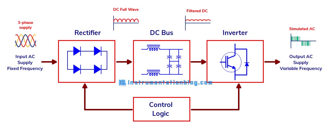
The rectifier section converts the AC input voltage into a DC voltage. The DC bus section consists of a capacitor bank used to smooth out the DC voltage from the rectifier section. The inverter section converts the DC voltage from the DC bus section and converted it back into AC voltage using IGBT, Transistors, etc.
The control circuit of the AC drive is used to control the frequency and voltage as well as parameterize the VFD. It is also used to start/stop the connected motor as well as give feedback about the status of an electrical motor to the operator.
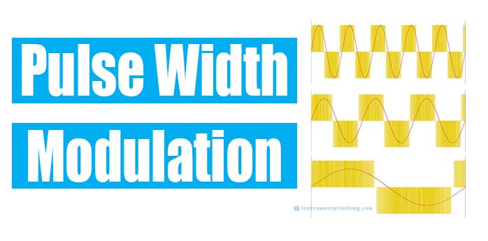
What is Pulse Width Modulation (PWM) in VFD?
The process of converting DC voltage into AC voltage in the inverter section of VFD is called Pulse Width Modulation(PWM).
Pulse width modulation uses transistors that on and off the DC voltage in a sequence to produce the desired AC output voltage and frequency. IGBTs (Insulated Gate Bipolar Transistor) are used as a transistor in VFD. The below figure shows the typical configuration of IGBTs in the inverter section of VFD:
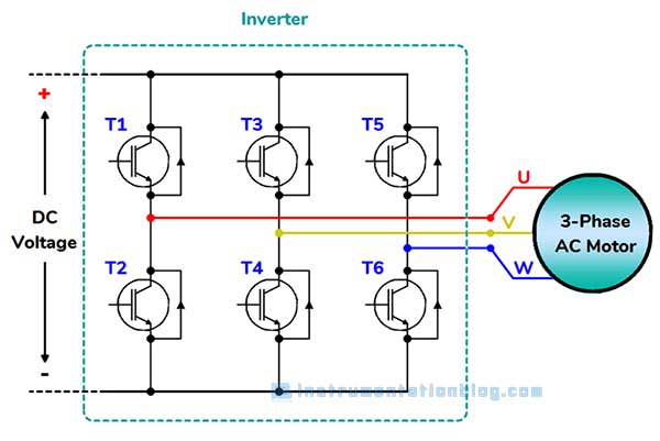
The IGBTs act as a switch between the DC bus voltage and motor windings. A variable frequency drive with an input voltage of 480 VAC, has a DC bus voltage of approximately 675 VDC. Thus the output of the inverter section has a voltage with an amplitude of approximately 675 VDC.
The PWM technique is used in VFD mainly to create a sinusoidal current waveform output to produce torque in the motor.
The one transistor on the top portion of the diagram and one at the bottom of the diagram must be activated to flow the current between two phases of the motor. Current can be induced in either direction between phases by utilizing the right combination of transistors.
As an example, if T1 and T4 are activated then the current will from DC bus positive terminal through the T1 transistor and U phase to the V phase and the T4 transistor to the DC bus negative terminal.
In the same way, when T2 and T3 are activated then the current will flow from DC bus positive terminal through the T3 transistor and V phase to the U phase and the T2 transistor to the DC bus negative terminal.
Another advantage of using PWM in VFD is the ability to control the amount of current going through the motor windings. This is done by varying the RMS voltage to the motor. The RMS voltage can be controlled by varying each pulse on and off time.
A longer ‘ON’ time of the pulse results in a higher RMS voltage across the phases.
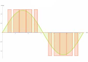
Image Credit: kebamerica.com
A shorter ‘ON’ time of the pulses results in a lower RMS voltage across the motor phases.
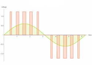
Image Credit: kebamerica.com
Thus the RMS voltage across each phase can be controlled by modulating the pulse width over each successive half. The resultant RMS voltage allows the VFD to vary the current flowing between motor phases.
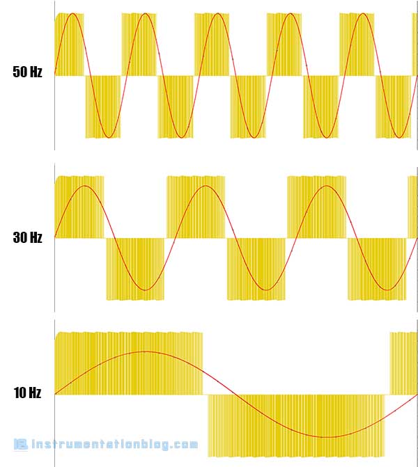
The simulated waveform produced by the pulse width modulation (PWM) techniques is also influenced by the switching frequency of the IGBTs.
The switching frequency of the IGBTs refers to the rate of on and off the individual transistor. Typical switching frequencies used are 4kHz, 8kHz, and even up to 16kHz. A higher switching rate will provide a cleaner waveform to the motor as there will be more pulses over each half-wave.
The motor speed can also be controlled by utilizing pulse width modulation (PWM). The resulting output waveform frequency can be changed by changing the period of the voltage pulses that induce the current in the motor phases.
The variable frequency drive controls both the output voltage and frequency of an electrical motor by coupling the control of pulse width and pulse group period.
VFD is widely used in industrial applications due to its ability to control both the torque and speed of an electrical motor. Motor speed can also be increased above the motor nameplate speed to achieve a higher production rate.
VFD can also be used to smooth start/stop the final equipment to reduce the mechanical wear and tear in mechanical components.
Next Must-Read Articles
- What is Variable Frequency Drive?
- The most used 3 Basic Motor Starter with its PLC Program!
- What is Temperature Scanner? How does it work?
- What is the Servo Motor? How does it work?
- How star-delta starter works?
- What is Soft Starter? How it works?
- Circuit Breaker Fundamentals.
- Relay Working and its importance in an electrical field.
You can read more articles about Electrical and you can also find books that boost your knowledge in the field of Instrumentation ⇒
Thanks for reading!
Very nice & helpful for sucess in carrer