The programmable logic controller has several converter instructions. Let’s study converter instructions in the Siemens PLC programming.
Till now you can see the various instructions of the PLC like Logic Gates, Bit Logic Instructions, 20+ Arithmetic instructions, PLC Timers and PLC Counters, etc.
There are 15 converter instructions you can find while programming. Let’s study each of these instructions in detail.
Table of Contents
Converter Instructions in PLC Programming
Integer to BCD conversion

This instruction converts the integer value into a three-digit Binary Coded Decimal value. It can convert integer value into BCD up to +/- 999.

Double Integer to BCD Conversion

This instruction converts the double integer value into a seven-digit Binary Coded Decimal value. It can convert double integer value into BCD up to +/- 9999999.

BCD to Integer Conversion

This instruction converts a three-digit Binary Coded Decimal value into an integer value.

BCD to Double Integer Conversion

This instruction converts a seven-digit Binary Coded Decimal value into a double integer value.

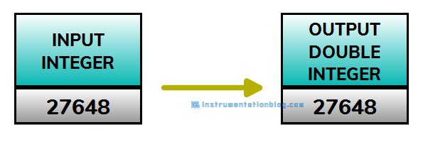
Integer to Double Integer Conversion

This instruction converts an integer value(16-bit) in double integer value(32-bit). The input parameter is a single word while the output parameter is the double word here.

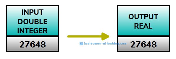
Double Integer to Real Conversion

This instruction converts a double integer value into a floating-point number.

Invert Integer(One’s Complement of Integer)

This instruction does the one’s complement with the 16-bit integer value and gives the output. Here both the input and output values are 16-bit.

Invert Double Integer(One’s Complement of Double Integer)

This instruction does the one’s complement with the 32-bit integer value and gives the output. Here both the input and output values are 32-bit.

Negative Integer(Two’s Complement of Integer)

This instruction does the two’s complement with the 16-bit integer value and gives the output. Here both the input and output values are 16-bit.

Negative Double Integer(Two’s Complement of Double Integer)

This instruction does the two’s complement with the 32-bit integer value and gives the output. Here both the input and output values are 32-bit.

Negative Real

This instruction multiplies the input floating-point number by -1 and gives the output. The input and output both here are floating-point numbers.

ROUND

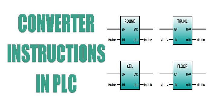
This instruction reads the input value as a floating-point number and converts it into a 32-bit double integer value. The result is the nearest integer number.

TRUNC

This instruction reads the input value as a floating-point number and converts it into a 32-bit double integer value. The result is the nearest integer number to zero.

CEIL

This instruction reads the input value as a floating-point number and converts it into a 32-bit double integer value. The result is the nearest integer number to the + infinity.

FLOOR

This instruction reads the input value as a floating-point number and converts it into a 32-bit double integer value. The result is the nearest integer number to the – infinity.

Summary
These are all the converter instructions in PLC. Please feel free to give your feedback in the comment section below. You can also find my previous tutorial about the plc programming instructions.
⇒ What is PLC? How does it work?
⇒ Logic gates using PLC ladder logic.
⇒ Basic bit logic instructions with PLC programming examples.
⇒ 5 different types of PLC programming languages.
⇒ Three different types of electric motor starter with its PLC program.
⇒ 30+ Most useful PLC communication protocols
You can also find the important questions and answers asked in the interview.
⇒ 25+ Most important questions asked in the PLC interview
⇒ Top 15 always asked questions in the SCADA interview
I hope you like this article. Please share this article with your friends and colleagues. Each share count for us. Thanks!
You can read more articles about Instrumentations and find the books that boost your knowledge in the field of instrumentation ⇒
