
Table of Contents
What is a Smart Transmitter?
Transmitters are used to measure physical variables such as temperature, pressure, level, etc. A transmitter converts the physically measured value into an electrical signal. Generally, an output signal is in the form of voltage(0-5V, 0-10V) or current(0-20mA, 4-20mA).
Even if this conventional transmitter is working fine, much industrial application demands more precision, performance, and reliability. Therefore, a smart transmitter is getting significance these days.
A smart transmitter is a device that is used a microprocessor as an integral unit. The smart transmitter has its own memory and it can also be programmed. It has abilities to perform calculations, do self-diagnostics, and can communicate with other devices.
The most common communication protocol on which the smart transmitter is communicating with other devices is HART Protocol. The HART stands for Highway Addressable Remote Transducer.
A transmitter compatible with HART protocol has two outputs: The conventional analog signal of 0-10V or 4-20mA and a digitally superimposed signal.

Block Diagram
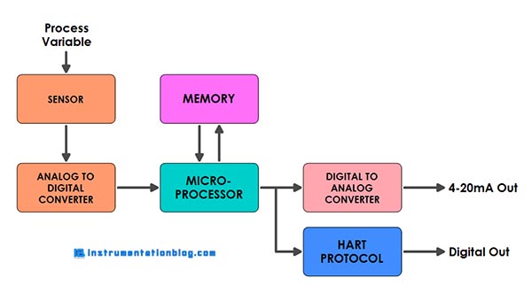
There are some integral parts of the smart transmitter, such as
1. Sensor or Transducer
2. Analog to Digital Converter
3. Micro-processor
4. Digital to Analog Converter
5. Digital Communication Protocol
Sensor or Transducer measures the physical signal from the process variable such as temperature, pressure, level, etc., and then converts it into an appropriate electrical signal. This electrical signal then applies to the Analog to Digital Converter.
The Analog to Digital converter converts the electrical signal into a digital count, which is a representation of process variable(PV) and then fed into the microprocessor.
The basic function of the microprocessor is a mathematical conversion of the digital count to the equivalent mA representation. However, the microprocessor has many algorithms fitted into it depending on the manufacturer. The output of the microprocessor is a digital representation of the desired output, which is we can see when we connect the hand-held field communicator to it.
The output of the microprocessor is fed into a Digital to Analog Converter, which converts the digital count value into an actual analog 4-20 mA electrical signal. This output is also known as current loop trip or 4-20 mA trim.
How can it differ from a conventional transmitter?
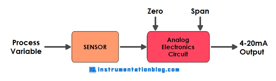
This is the simplest block diagram of the conventional analog transmitter. The conventional transmitter accepts signals from the sensor and then directly fed into a set of electronics circuits, which then converts this signal into an appropriate electrical signal and gives output in the form of a 4-20mA loop current.
Key differences between smart transmitter and conventional transmitter:
√ Communication
The smart transmitter has a digital communication protocol, generally works with the HART protocol. This digital communication protocol allows a smart transmitter to superimpose the analog signal.
While in the conventional transmitter, the output is in the form of a 4-20mA loop current, which doesn’t allow user digital reading.
√ Accuracy
The zero and span adjustment in the conventional transmitter is limited by 2-3% of the fixed reading value.
While smart transmitter provides a better display of parameters that is showing information about zero and span adjustment, instrument loop identification, diagnostics, and multiple process variables.
√ Rangeability
The turndown rangeability can be high as 100:1 in the smart transmitter as compared to the rangeability as 15:1 or 20:1 in the conventional analog transmitter.
Advantages of Smart Transmitter
⇒ Improved Accuracy and Repeatability
⇒ Long term stability
⇒ Almost minimal maintenance cost
⇒ Remote calibration is possible and provides a facility of re-ranging
⇒ Has its own memory to store information about the last calibration
⇒ Self-calibration and self-diagnosis approach
⇒ Faulty detection approach
I hope you like this article. If you want more articles then please comment down below.
Next Must-Read Articles:
⇒ How does a solenoid valve work?
⇒ How does a temperature scanner work?
⇒ Difference between 2, 3, and 4-wire RTD?
⇒ What is a Servo Motor? How does it work?
⇒ Basic Fundamentals about 4-20mA Current Loop
You can read more articles about Electrical and you can also find books that boost your knowledge in the field of Instrumentation ⇒
Thanks for Reading!