Table of Contents
What is Lubrication Oil Pump System?
Lubricating oil pumps are used to provide continuous cool, clean oil to the bearings, gear, etc. at the proper pressure, temperature, and flow rate.
How the system works?
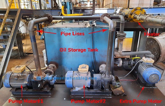
The lubrication oil pump system uses a tank or reservoir to store a huge amount of oil.
Now in the case of circulation lubrication, the lubricating oil pump takes an amount of oil from the tank or reservoir and then forces it through the lubrication points and then feeds it back to the tank or reservoir.
The system also uses the oil cooling or filtration system in between the path to cool and filter the oil.
The lube oil pumps are used to maintain a static pressure to feed the oil to the different lubricating points, this pressure is continuously monitored and if there will be a drop due to any fault a redundant lubrication oil pump takes in charge to maintain the pressure.
Components used in the system
The components that are used in the lubrication oil pump systems are as below:
- Oil Storage Tank or Reservoir
- Main and Auxiliary Lube Oil Pumps
- Coolers
- Filters
- Pressure Switch
- Temperature Controller with Sensor
PLC Program to implement the Redundant Lubricating Oil Pump System
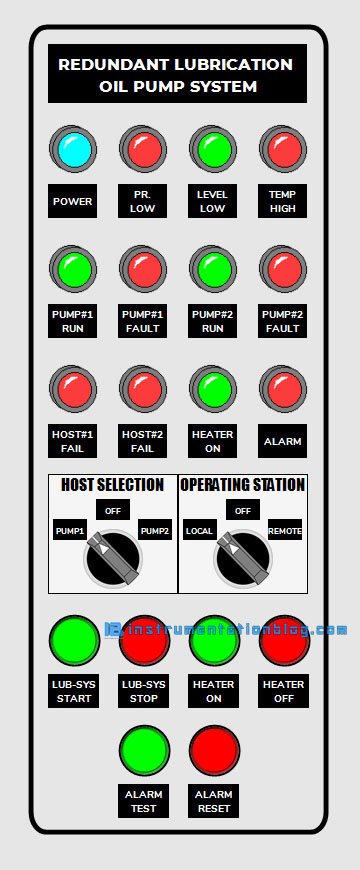
The above image is showing the control desk of the lubrication oil pump system. The control wiring for this desk is as below:
There are several sensors installed in the lubrication oil pump system like a temperature sensor to measure the temperature of the oil in the storage tank or reservoir, level switches installed at both tops as well as bottom to know the level of the oil in the storage tank, pressure switch to know whether the pressure in the circulation oil system is normal or below the mentioned set point.
Relays, as well as indicators on the control desk, are installed to know the feedback.
The wiring for the PLC digital inputs are as below,
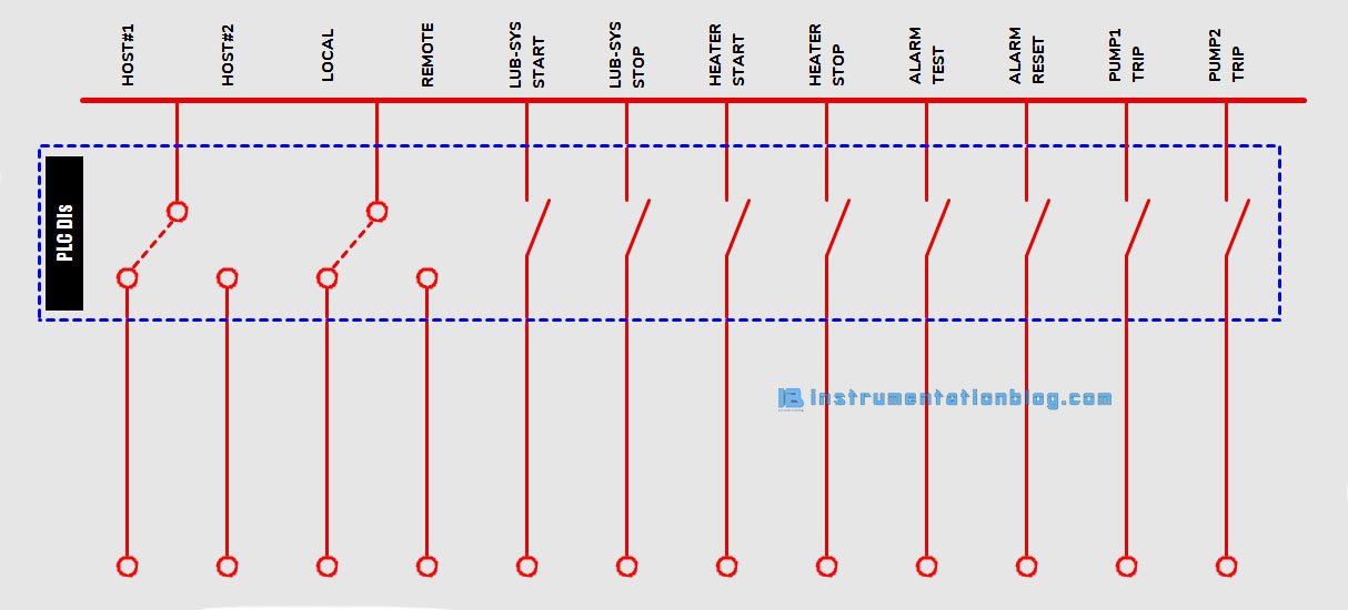
Digital inputs like selector switches(Host Selection and Operating Station Selection), push buttons like lubrication system start, lubrication system stop, heater start, heater stop, alarm test, alarm reset and feedbacks from the thermal overload or microprocessor relays of pumps are directly wired as a PLC digital inputs.
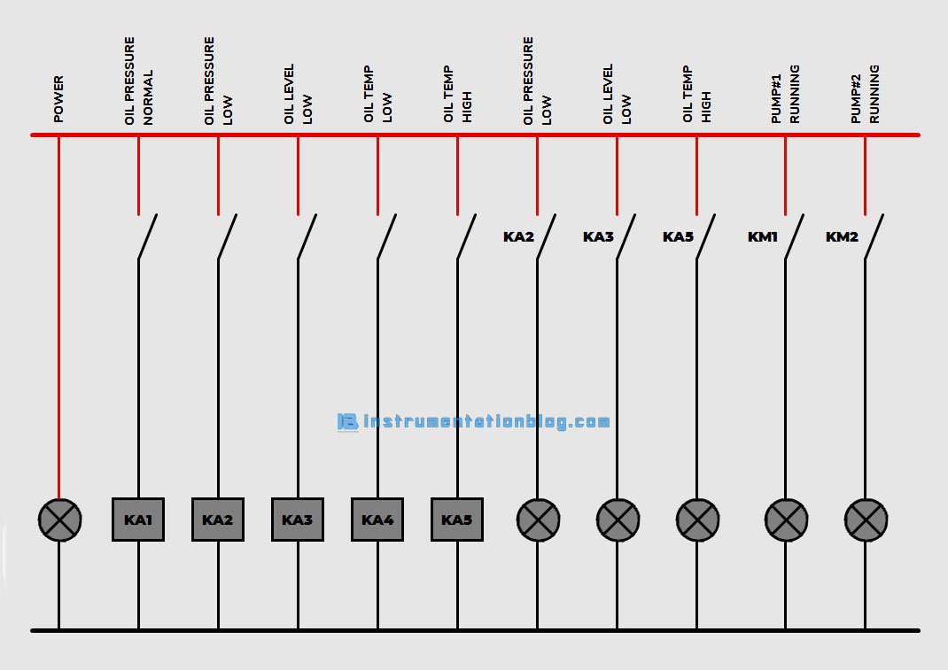
The wiring for the PLC digital outputs are as shown in the below figure,
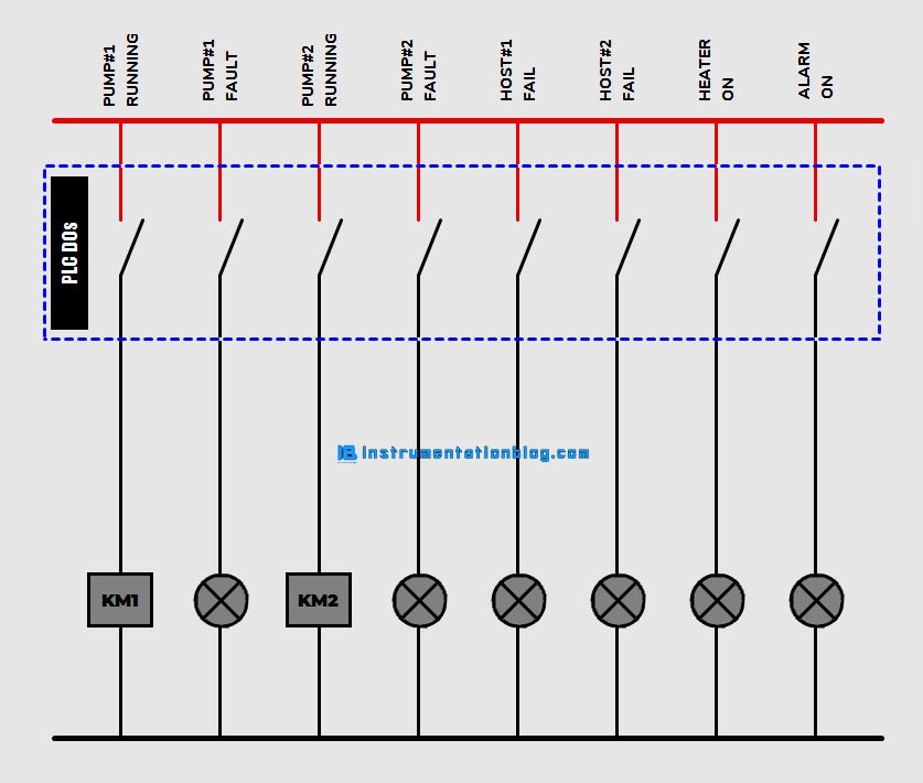
Digital outputs from the PLC for the pumps start or stop, pump fault, hosts fail, heater on or off, alarm present, etc. are directly wired to the contactor and indicators on the control desk.
Implementation of PLC Ladder Logic
Here you can find the implementation of the lube oil system in the PLC ladder language,
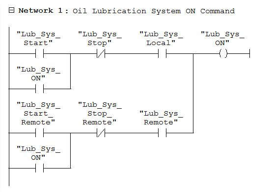
Network#1
This is the logic to start and stop the lubrication oil pump system, Also you can find the selection of remote or local from where the operator wants to start the system in the logic.
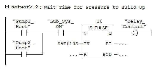
Network#2
As soon as the system starts, the system will wait for the given time, which is 10 sec in this case, for the pressure to build up in the system.
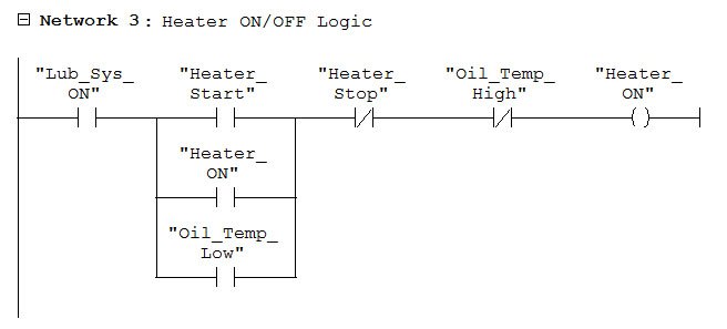
Network#3
In this network, you can find the logic to start and stop the heater which is used to maintain the temperature of oil in the storage tank or reservoir.
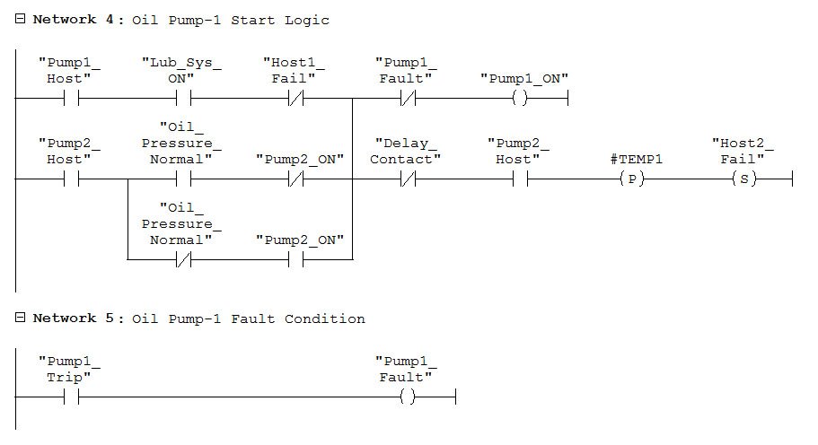
Network#4-5
Here is the logic to start and stop the lube oil pump-1 when pump-1 is selected as a host as well as the logic to change the redundant oil pump when the host fails.
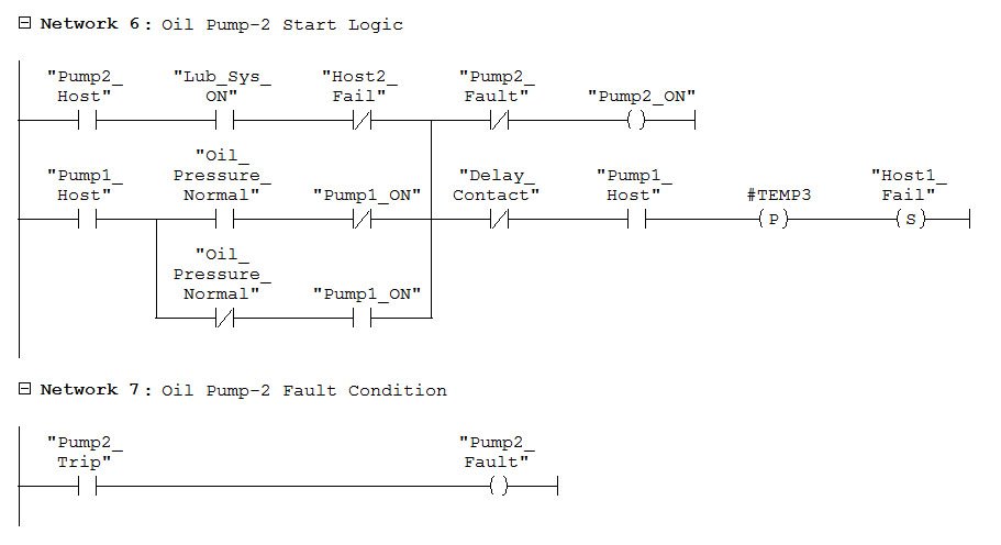
Network#6-7
Here is the logic to start and stop the lube oil pump-2 when pump-2 is selected as a host as well as the logic to change the redundant oil pump when the host fails.
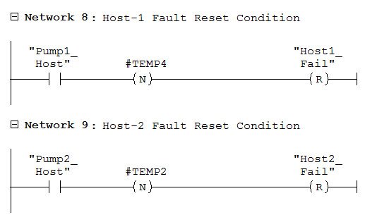
Network#8-9
Below is the logic to reset the host fail indication during the start-up as well as the while changing the host.
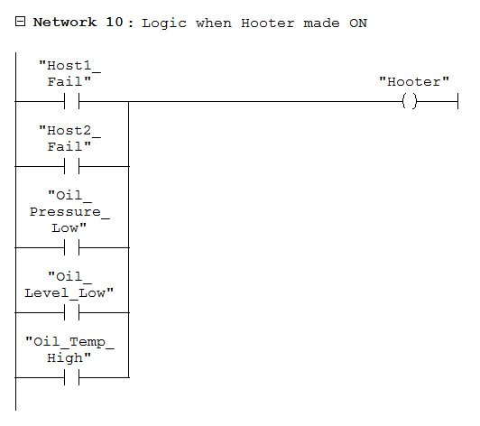
Network#10
There are several fault conditions when the operator needs to pay attention, that conditions generate an alarm in the form of the hooter.
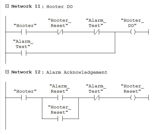
Network#11-12
These networks show the test and acknowledge the alarming hooter while diagnosing a problem on the system.
Solutions
The logic shown as above gives the user a solution of the main two problems ⇒
- When any of the hosts – Oil Pump#1 – fails due to overload or overcurrent. The redundant – Oil Pump#2 – takes responsibility to maintain the pressure without losing it. Also, the system gives an operator an information/indication about the host failure. So that maintenance personnel will start to troubleshoot the problem.
- When oil pressure goes below the down limit due to fault in the pipeline or any other problem except a motor overload, the redundant oil pump starts. Also, in this case, an operator gets information/indication about the host failure as well as pressure drop.
I hope you like this article about the lube oil system with redundancy and implementation in PLC ladder language.
You can comment down below for the feedback. If you want more practical examples with their implementation in PLC then you can write it down in the comment section or mail me from the contact us page.
Thanks!
To find the different products related to the PLC system ⇒ Click here
You can also find the books to boost your knowledge in Instrumentation and PLC by clicking the below link ⇒
Instrumentation and Control related books, PLC related books, SCADA related books
You can find important QnAs like,