Table of Contents
How to calibrate a Differential Pressure Transmitter?
What is differential pressure?
Differential pressure is the pressure measured between two different pressure points, usually known as DP or ΔP.
Differential pressure is widely used in domestic as well as industrial applications. The DP measurement is necessary during flow measurement. Also, it is necessary sometimes to know the level, density, viscosity, or even temperature.
As we have said that DP measurement is necessary to know the flow rate. By measuring the difference in fluid pressure while the fluid flows through the pipe we can calculate the flow rate.
Instruments are used to create a differential pressure.
Generally, Flow measurement includes primary and secondary elements. The primary element produces a difference in pressure as the flow increases. The most common types of primary elements are Orifice, Venturi, Pitot tube, etc.
What is a Differential Pressure Transmitter?
The secondary element is a differential pressure transmitter, which measures the pressure difference produced by the primary element. The differential pressure measurement mustn’t be affected by changes in the fluid pressure, temperature, or other properties such as ambient temperature.
The common output of the DP transmitter is an electrical signal like 4-20mA. But it may also include digital communication like HART, Profibus Fieldbus, Modbus, etc.
Material required to calibrate a differential pressure transmitter.
- Power Supply 24V DC
- Multi-meter
- Instrument Calibrator(Hart)
- Pressure Source(Scandura)
Procedure to calibrate a differential pressure transmitter.
⇒ Record all the details of the differential pressure transmitter, such as
- Calibration Range
- Span
- Maximum Working Pressure
- LRL(Lower Range Limit)
- URL(Upper Range Limit)
Before going to the next steps, there are some common terms used in DPT(Differential Pressure Transmitter) which you need to know about,
LRV (Lower Range Value): It is the lowest value of the transmitter output, if your transmitter output is 4 to 20 mA then in this case it will be 4mA.
URV (Upper Range Value): It is the highest value of the transmitter output, if your transmitter output is 4 to 20 mA then in this case it will be 20mA.
LRL (Lower Range Limit): It is the lower value of the transmitter calibration range, suppose if your transmitter is calibrated at 0 to 1000 Pa then in this case it will be 0 Pa.
URL (Upper Range Limit): It is the highest value of the transmitter calibration range, suppose if your transmitter is calibrated at 0 to 1000 Pa then in this case it will be 1000 Pa.
Span: Span is defined as the difference between the Upper Range Value and the Lower Range Value of the transmitter. Span = URV – LRV.
Instrument Range: The instrument range is the capacity to measure the pressure at the defined region. If the manufacture is giving the instrument range 0 to 1000 Pa, then 0 Pa is our lowest limit and 1000 Pa is our highest limit at which we can calibrate the instrument.
Calibration Range: The calibration range is the defined region in which the instrument can be calibrated this range must be under the instrument range.
MWP (Maximum Working Pressure): Maximum working pressure is the limit up to which the transmitter can withstand.
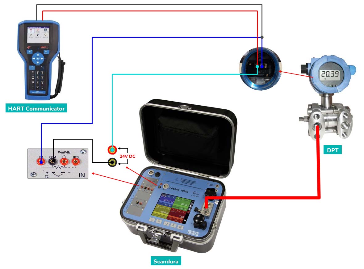
⇒ Connect an instrument as per the diagram shown below.
⇒ If you are using a manifold after the differential pressure transmitter, then make sure that the equalizing valves are closed and two block valves, high and low, are open.
⇒ Most of the transmitters are calibrated at five points, such as 0%, 25%, 50%, 75%, and 100%. Readings should be taken on both sides such as increasing inputs and decreasing inputs.
⇒ Connect the pressure source to the high-pressure port of the pressure transmitter and let the low-pressure port of the transmitter open to the atmosphere for the reference pressure.
⇒ Apply the pressure inputs such as 0%, 25%, 50%, 75%, and 100% of the total span. Note the transmitter output in mA at each stage. Now we are ready to calibrate a differential pressure transmitter. Now, we have all the data of the pressure transmitter.
⇒ Apply the 0% pressure(LRL) at the high-pressure port, let the low port of the transmitter be open to the atmosphere so that there is no differential pressure between high and low-pressure ports. Now check for the zero reading(LRV) in the transmitter, if you are not getting it then adjust it from the HART communicator.
⇒ As soon as the correct zero reading is established, the next step is to adjust the span. Apply the 100% pressure(URL) and then check for the reading at transmitter output, if you are not getting 20mA(URV) then adjust the reading from the HART communicator.
⇒ After correcting the span we need to again check the zero reading, it may be required to adjust again in some cases.
⇒ After adjustment of correct zero and span, Note the transmitter output at each stage in increasing and decreasing order both. Check for the error if it is in the plant acceptable range then you are done with the calibration.
Next Must-Read Articles
- What is a Differential Pressure Transmitter?
- Bellow Pressure Gauge – The complete tutorial.
- How does a Diaphragm Pressure Gauge work?
- What is a Smart Transmitter? Features of a Smart Transmitter.
- Overview of Bourdon Tube Pressure Gauge.
You can read more articles about Electrical and you can also find books that boost your knowledge in the field of Instrumentation ⇒
Thanks for reading!