Are you searching about what is control systems? Where these systems are used? What are there types? etc.
If yes, then you are in the right place.
Before going to the control systems, first, let’s consider some examples like,
- Automatic water level control of a boiler tank.
- Automatic temperature control of the furnace.
- Automatic pressure control of an air compressor.
- Automatic flow control through a weighing feeder control system.
- Automatic gas pressure control in a furnace.
- Automatic position control of a control valve.
There are lots of examples in which control systems are used. And I hope that you want to know how this system works?
You’ll get all the answers after reading this article. So without wasting much time let’s start this blog.
Table of Contents
What is Control Systems? Open loop and Closed loop control systems
Control System is defined by Wikipedia,
“A control system manages, commands, directs, or regulates the behavior of other devices or systems using control loops.”
A control system is a set of devices that are used to build a system that generates the desired output. In this modern era of technology, the control system plays an important role.
Nowadays in day-to-day tasks, many types of equipment or machines are using some forms of control system like washing machines, coffee makers, geysers, automatic iron, automatic water filling tank, air conditioner, etc.
In the field of industries, Automation highly requires control systems or elements.
The main aim of the control system is to maintain a healthy relationship between the input and output.
Requirements of Good Control System:
- Accuracy
- Sensitivity
- Stability
- Speed
- Oscillation
Types of Control System:
There are mainly two types of control system:
- Open loop control system
- Closed loop control system
Open loop Control System

As shown in the figure, in an open loop control system, control action is totally independent of the output system as there is no feedback from the output to the input.
So when there is no feedback from the output system to the input, it is referred to as the open loop control system.
A manual control system is also called an open loop control system.
Practical Examples
Electrical Hand Dryer, Hair Blower, Water Heater, Dish Washer are some of the day-to-day equipment of open loop control system.
Advantages
- They are simple in construction
- Easy to maintain
- Economical
Disadvantages
- They are not much accurate
- They are somewhat not reliable as output is not measurable
Closed Loop Control System
The control system in which the input quantity will be adjusted based on the output generated is referred to as a closed loop control system.
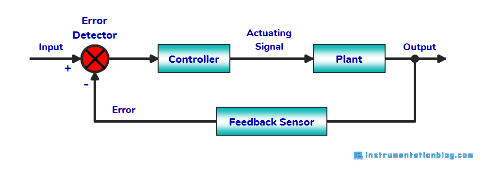
As shown in the figure, there is a feedback from the output system to the input. A controller or control system changes the flow of input according to the difference between input and feedback from the output.
This procedure repeats itself in an automatic manner. So we can call it also an automatic or a feedback control system.
Practical Examples
Air-Conditioner, Automatic Water level controller, Automatic Electric Iron are some of the equipment in day-to-day examples of a closed loop control system.
Advantages
- They are more accurate as the output is measurable
- They are more stable
- We can customize the relationship between input and output systems
Disadvantages
- The initial cost is high
- Somewhat complicated to design
- They require frequent maintenance
- Stability issue when outputting effects from external aspects
Comparison of Closed loop and Open loop Control Systems:
| Sr. No. | Open loop control system | Closed loop control system |
| 1 | There is no feedback. | There is feedback in this system. |
| 2 | Very easy to design. | Sometimes it’s complicated to design. |
| 3 | Very less initial cost. | It is costly. |
| 4 | Less maintenance required. | Frequent maintenance required. |
| 5 | The error detector is absent. | There must be an error detector. |
| 6 | It is stable. | It may become unstable. |
Closed loop control system examples using PLC and VFD
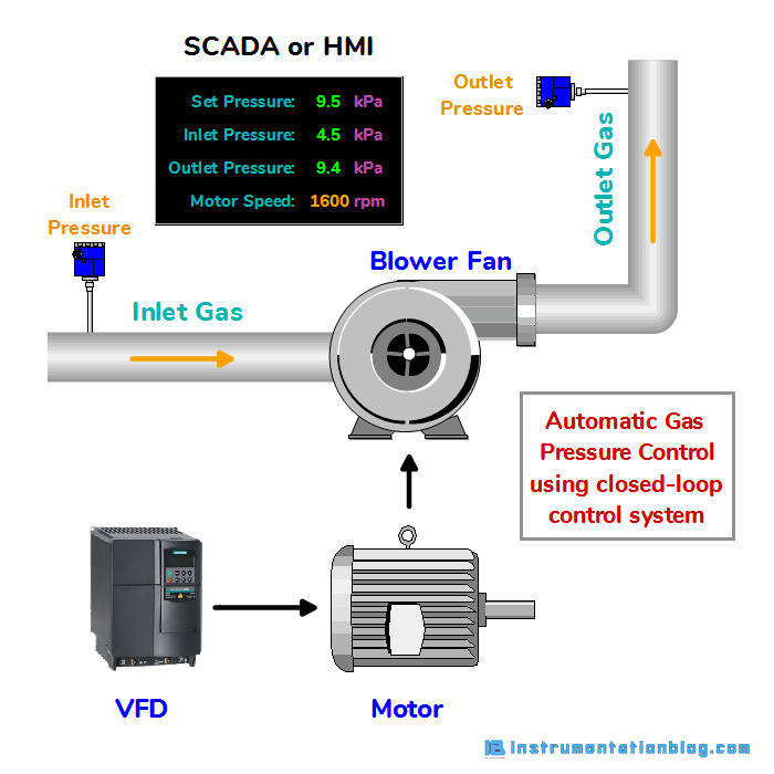
Here is the example of Automatic Gas Pressure Control using PLC and VFD. Here in this example, we are maintaining the gas pressure at the desired value by giving input from the SCADA or HMI. Also, Implement this program in PLC using ladder logic programming language.
Main Objective:
The main objective is to control the gas pressure at a preset value. We are using an AC drive to run the induction motor which is connected with the blower fan. To measure the inlet and outlet gas pressure, Sensors are installed at both places.
⇒ Now when the output pressure is less than the set pressure, then the AC drive starts increasing the rpm of the blower fan.
⇒ And when the output pressure is greater than the set pressure, then the AC drive starts decreasing the rpm of the blower fan.
Steps for the Solution:
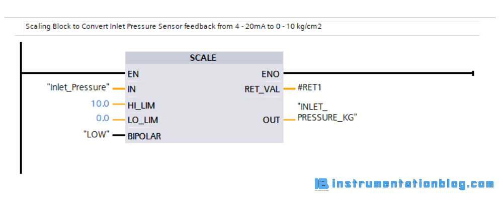
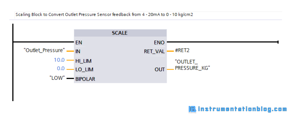
⇒ Convert the feedback of the pressure sensors from 4 – 20mA to appropriate value using scaling block.
⇒ Convert the feedback of the actual speed from 4 – 20 mA to appropriate value using scaling block.
⇒ Compare the value of the output pressure with the set pressure and commands the AC drive either to increase or decrease as per the comparison.
⇒ Convert the set speed value to 4 – 20mA using an unscaling block.
PLC Program for this solution:
The below images shows the conversion of the closed loop control systems into PLC ladder language logic.
⇒ The below figure shows a scaling block that does ADC conversion of Inlet pressure sensor feedback of 4 – 20mA into 0 – 10 kg/cm2.
⇒ The below figure shows a scaling block that does ADC conversion of Outlet pressure sensor feedback of 4 – 20mA into 0 – 10 kg/cm2.
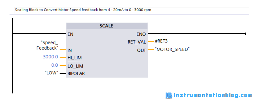
⇒ The below figure shows a scaling block that does ADC conversion of Motor Speed feedback of 4 – 20mA into 0 – 3000 rpm.
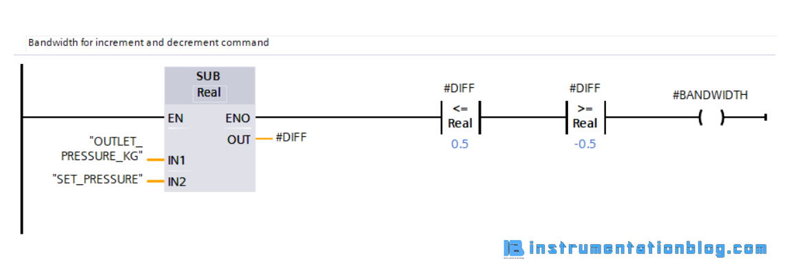
⇒ The below figure shows a bandwidth logic like we have given a set pressure to 8 kg/cm2 and if the outlet pressure we have received within the 7.5 kg/cm2 to 8.5 kg/cm2 that is within the ±0.5kg/cm2 than this closed loop control doesn’t work.
This is the network that decides the bandwidth for the closed loop control system.
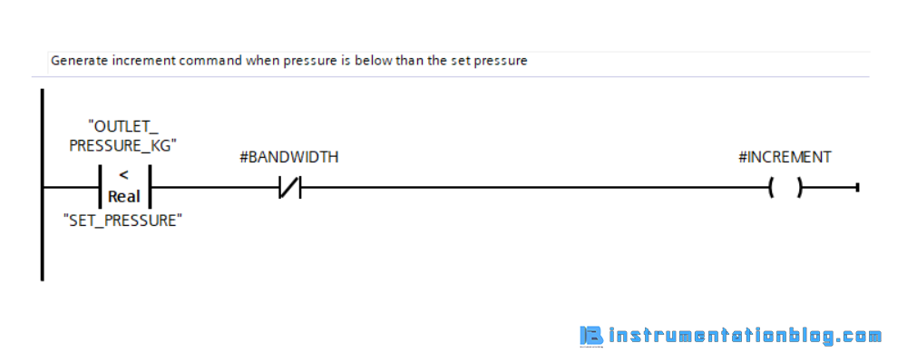
⇒ The below figure shows when the set pressure is below than the outlet pressure and outside the bandwidth area then it will generate increment command.
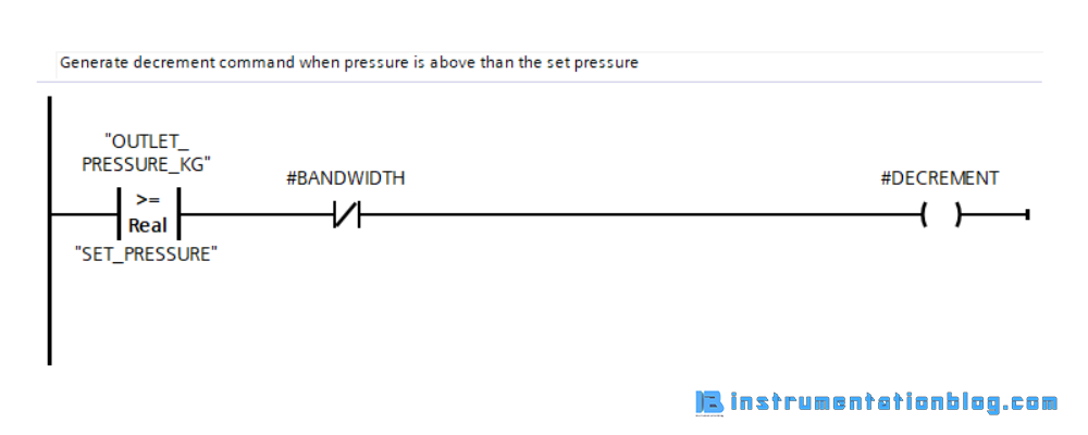
⇒ The below figure shows when the set pressure is above than the outlet pressure and outside the bandwidth area then it will generate decrement command.
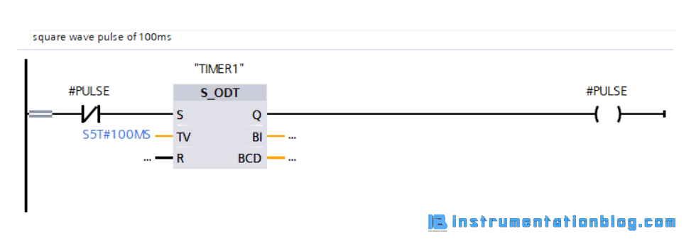
⇒ The below figure shows a square wave of 100ms that is the time to give the command to increment or decrement the motor speed by 10 rpm.
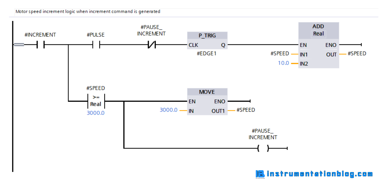
⇒ The below figure shows a logic to give the command to increment the motor speed.
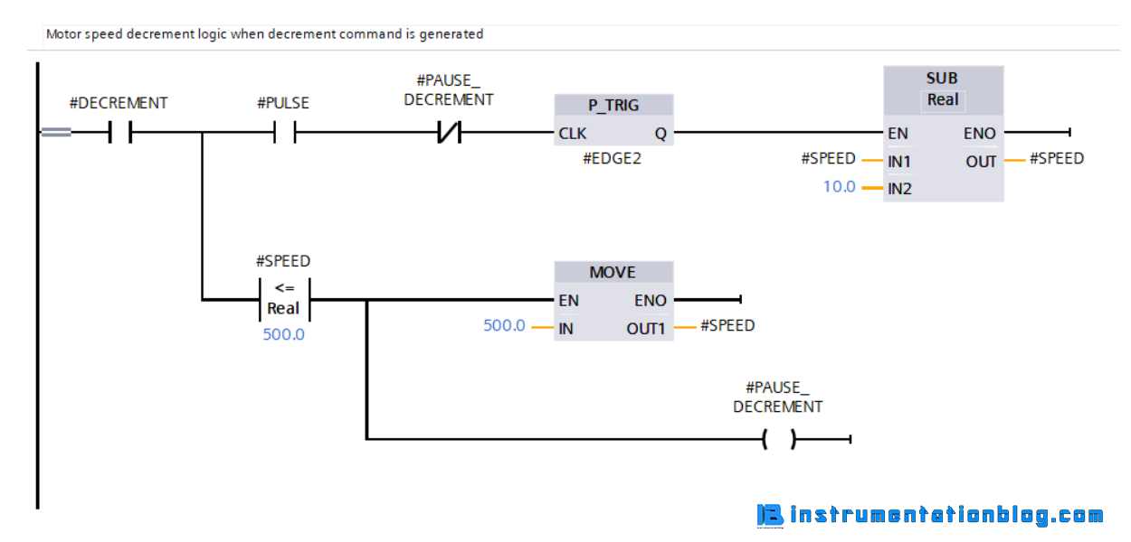
⇒ The below figure shows a logic to give the command to decrement the motor speed.
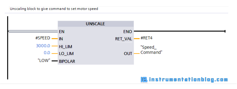
⇒ The below figure shows an unscaling block that does DAC conversion of motor speed rpm from 0 – 3000 rpm to 4 – 20mA.
(Note: This is the basic implementation of the closed loop control system of this example. You can implement in many advanced ways using PLC internal PID blocks. If you want to know more about PLC internal PID block then comment down below)
Final Words (Open Loop vs Closed Loop Control System)
I hope all of you got all the basic details related to the control systems. We have seen basic overview related to the control systems, their types and practical examples.
We have seen the practical implementation of the closed loop control system in the plc program ladder language. Hope you like it. If you want more plc tutorials like this then don’t forget to comment down below.
Till then thank you for reading and sharing this blog.
very important job and I like this job
very nice and simple explanation , easy to understand…
however can you elaborate more on the meaning of the input and out put , function on the block . e.g. ret_val and other.
sorry if i ask basically. i am a beginner.