Table of Contents
Difference between 2-wire, 3-wire, and 4-wire RTD configuration
Resistance Temperature Detector(RTD) is the most popular temperature sensor in the industry. RTDs work generally with three different configurations such as 2-wire, 3-wire, and 4-wire.
What is the best configuration of RTD?
The answer depends on the application as well as the number of factors such as initial cost, space, environment, accuracy requirement.
As we know that the RTD is a temperature sensor that changes its resistance according to temperature. The output of the RTD is a resistance that varies according to the temperature.
Every RTD has a sensing element including lead wires, connector, and measuring instrument itself. So, there may be a chance of getting additional resistance into the circuit. Therefore, it is important to eliminate this unwanted resistance from the measuring circuit.
The configuration of the circuit determines how accurately the RTD’s resistance can be calculated and how much is the distortion of the extraneous resistance in the circuit?
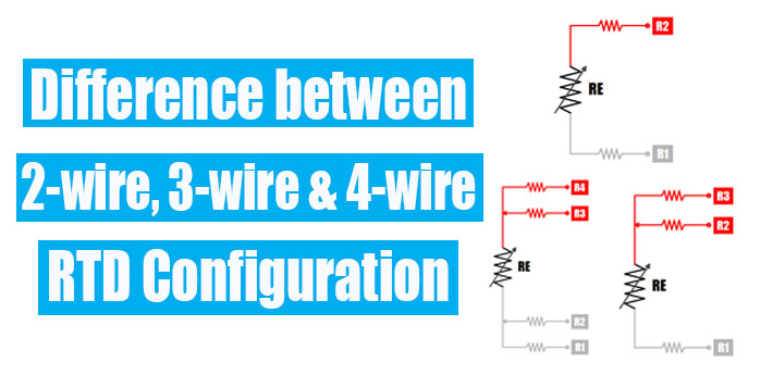
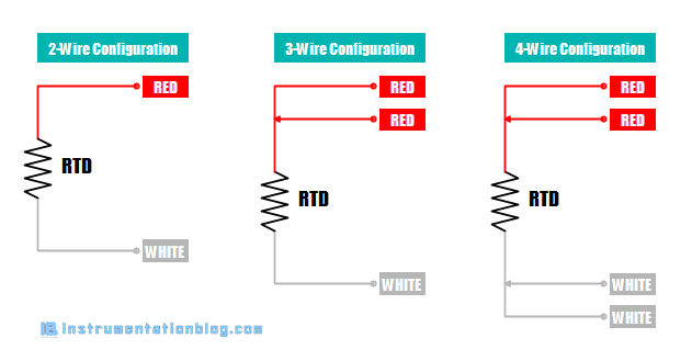
There are three types of wire configurations: 2-wire, 3-wire, and 4-wire.
2-Wire RTD Configuration
The 2-wire RTD configuration is the simplest among all the RTD circuit design. In this configuration, a lead wire is directly connected to the measuring device.
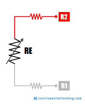
Therefore, it contains the resistance of the RTD element, lead wires, and measuring instrument itself. The final result must contain some degree of error.
However, high-quality lead wires and connectors can reduce some amount of error but it is not possible to eliminate the entire error from the measuring circuit.
2-wire RTD configuration is mostly used in short-distance measurement and where a high degree of accuracy is not required in the system.
3-Wire RTD Configuration
The 3-wire RTD configuration is the most commonly used RTD configuration among industries. In this configuration, one extra lead wire is added on one side of the RTD element. Therefore, we can find two lead wires on one side of the element and one lead wire on the other side.
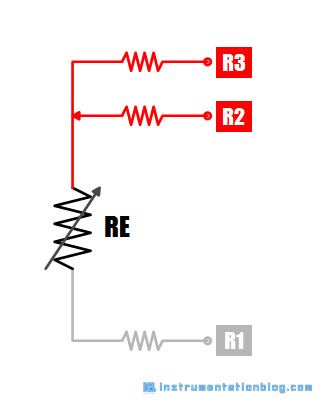
This type of configuration can cancel lead wire resistance from the measurement when measuring instruments also use a 3-wire configuration.
How this 3-wire configuration cancels the lead wire?
The resistance of all three lead wires is equal, that is R1=R2=R3. The resistance between the lead wires 1 and 2 are R1+R2+RE and the resistance between lead wires 2 and 3 are R2+R3.
Therefore, overall resistance using a 3-wire configuration can be (R1+R2+RE) – (R2+R3). Because all the lead wire resistance is the same the result will be RE only, that is the resistance of RTD elements only.
4-Wire RTD Configuration
The 4-wire configuration is the most complex and expensive configuration among all the three configurations, but it provides an accurate result. We will find the two lead wires on both sides of the RTD element in the 4-wire configuration.
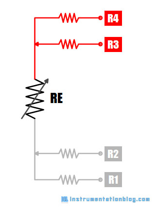
In this configuration, the two wires, one from each side of the RTD element, are used to measure the current between the sensing element, and the other two wires are used to measure the voltage drop.
As an example, the constant current will pass through the outer leads 1 and 4. The constant current generator will generate an accurate current even though there is some resistance in the leads.
And the voltage drop is measured across the inner leads 2 and 3. There is practically no current in these wires and even though there would be any resistance, it does not cause any voltage drop. So there will be no error.
The 4-wire RTD configuration fully eliminates all the lead resistance and will generate an accurate result. A 4 wire RTD connection is mainly used in laboratories and where a high degree of accuracy is required.
Summary
I hope you like this article. Please comment and send us ideas to write more articles about instrumentation.
Some important points to remember ⇒
1. Always use a 4-wire configuration while calibrating an RTD.
2. Always connect 3 wires in the temperature transmitter when using a 3-wire RTD in the field.
3. Never use a 2-wire RTD configuration when you require a high degree of accuracy.
You can also read,
