Table of Contents
The Fundamentals of 4 to 20 mA Current Loop
Introduction
There are various types of sensors available in the process instrumentation field like thermocouple, RTD, thermistor, pyrometer, etc. in Temperature Sensors, Resistive, Capacitive, Inductive in Pressure Sensors, DPT(Differential Pressure Transmitter), Flow Measurements.
All these sensors provide an analog signal as an output to display the reading. Analog signals are the information provided by the instruments in the form of voltage or current. They are predominant types of input in industries. Out of all these analog signals, 4-20 mA current loop is the dominant standard in the process industry.
Today many of us do not have the basic fundamental knowledge about how to set up a 4-20 mA current loop, how to use a 4-20 mA current loop, What are the pros and cons of 4-20 mA current loop. This potentially cost you while taking a decision to use it in the process field.
So in this article, we are going to see about the basic fundamentals of 4-20 mA current loop, how to use it, and control it?
What is 4-20 mA Current Loop?
To understand, what is the 4-20 mA current loop? we need to first understand a simple circuit shown below, which is working on ohm’s law.

Ohm’s law saying that voltage(V) is equal to the current(I) multiplied by the resistance(R).
Voltage (V) = Current (I) x Resistance (R)
This is the fundamental equation of electrical engineering. Consider a simple DC circuit to understand the basic principle on which 4-20 mA current loop is working,
There is the main power supply labeled with Vmain and three different loads which can be controller, display, meters, etc in the real field. Now the supply voltage is the 12 V providing by the Vmain.
The voltage drop across each load can be calculated using ohm’s law as an example voltage drop across the load R1 is i x R1. Each element in the loop has a voltage drop, however, current(i) is the same everywhere in the loop. This is the basic principle on which 4-20 mA current loop is working.
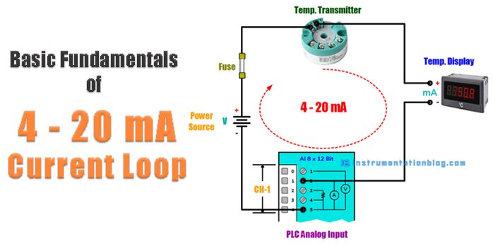
Now let’s take an example of a real field. You can see the 4 to 20mA circuit current loop as shown below.
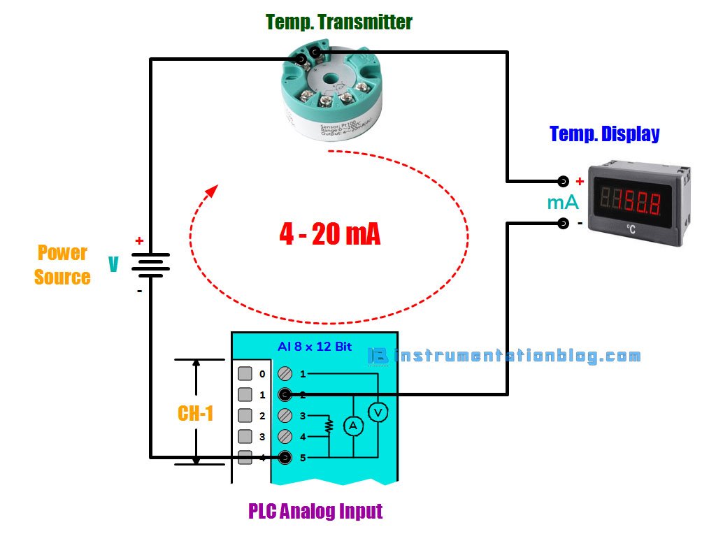
There is a temperature transmitter, PLC, Temperature Display, and Voltage Source in a loop. Each element in the loop has some voltage drop. To work the loop correctly, we must have some calculations. This is what we called as Loop Budget.
The maximum current in the loop is 20 mA. As per ohm’s law Voltage = Current x Resistance
⇒ The loop voltage required for the transmitter is 8 V as per the datasheet.
⇒ The internal resistance of the PLC AI is 250 Ω as per the datasheet, so the loop voltage required is 0.020 A x 250 Ω = 5.75 V
⇒ The resistance of the temperature display is 350 Ω, so the loop voltage required is 0.020 A x 350 Ω = 8.05 V
Finally, all the resistance in the loop is considered except the internal resistance of the wire. If the length of the wire is 80 meters and the cross-sectional area of the wire is 0.445 mm2. Then total resistance of the wire becomes 10.7 Ω. Then the loop voltage requirement is 0.020 A x 10.7 Ω = 0.25 V.
Now, the overall calculation of all the elements in the loop are,
⇒ The voltage required by the Temperature Transmitter = 8 V
⇒ The voltage required by the PLC AI = 5.75 V
⇒ The voltage required by the Temperature Display = 8.05 V
⇒ The voltage required by the loop wire resistance = 0.25 V
⇒ Total voltage required in the loop is 8 V + 5.75 V + 8.05 V + 0.25 V = 22.05 V
⇒ The voltage supplied in the loop is 24 V.
⇒ The voltage remaining to power the other loads in the loop is 24 V – 22.05 V = 1.95 V.
Now we know that the loop has more than enough power to drive 20 mA through all the connected loads in the loop.
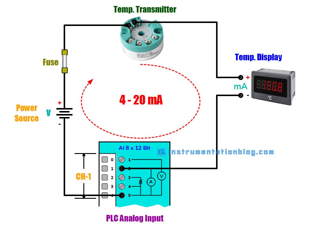
Another thing is loop should always be protected from the short circuit current by adding a fuse with an appropriate rating to the loop. If a short circuit occurs in the loop, the fuse blows, and the current will drop to 0 mA.
Why 4-20 mA Current Loop?
The 4-20 mA current loop is the dominant method for transmitting the sensor’s information over a long distance in the process industries.
Now as shown below figure there is a sensor that measures the physical parameters such as temperature, pressure, speed, flow, etc. The sensor has to transfer this information in the form of electrical signals like voltage or current.
Transmitting sensor information over a long distance in the form of current is particularly useful.
The sensor’s output voltage is converted into a proportional current, 4 mA represents the zero level of the output and 20 mA represents the full-scale output. Then a receiver at the remote location end converts this 4-20 mA signal back to the voltage which is then processed by a controller or a display signal.
Transmitting sensor information in the form of voltage over a long distance has several drawbacks. There may be a chance of voltage drop due to wire internal resistance and receiving low voltage at the receiving end.
Components of 4-20 mA Current Loop
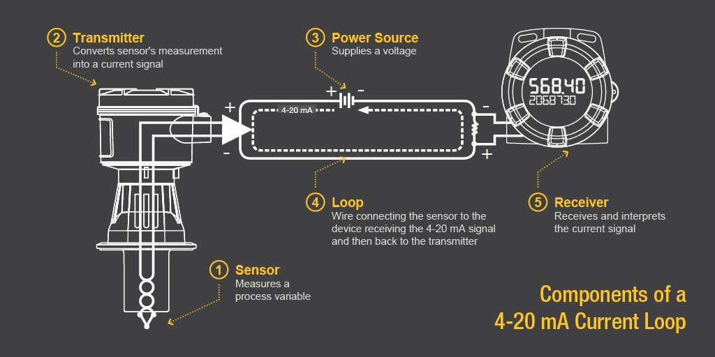
image source predig.com
There are some components that you have to understand in the 4-20 mA current loop:
Sensor
A sensor is a device that is used to measure the field parameters like temperature, pressure, flow rate, etc.
Transmitter
The sensor needs a device to convert the measured parameter into an appropriate electrical signal. The transmitter fulfills this criterion, it converts whatever sensor is monitoring into a current signal between 4 to 20 mA.
If there is an RTD that is used to measure the temperature between 0 to 400 ºC, and it is measuring 200 ºC right now then the transmitter converts it into 12 mA.
Power Source
To generate the output, there must be a power source. We need to remember that the power source must supply a DC current.
Many common voltages are used with 4-20 mA current loop like 9, 12, 24 V, etc. depending on the setup. It is important that the power supply must be greater than 10% of the total voltage drop across the loop.
Loop
With the appropriate power supply, there needs to be a loop, which refers to the actual wire connecting the measuring sensor to the device receiving 4-20 mA and then back to the transmitter.
The current signal on the loop is regulated by the transmitter according to the sensor’s measurement. The total voltage drop across each element in the loop must be less than the total voltage supplied by the power source.
Receiver
The receiver is a device in the loop that interprets the current signal. The current signal is translated into a unit that can be easily understood by the operator.
The receiver displays the information by the display or does something with that information. Digital displays, controllers, actuators, and valves are common devices to incorporate the loop.
Pros and Cons of 4-20 mA Current Loop
4-20 mA current loop advantages
⇒ Line losses are not usually significant: The fact that a current source is used means that voltage losses caused by line resistance are unlikely to cause a problem.
⇒ Can be used for long distances: As voltage losses are not normally significant, 20 mA current loop systems can be sued for carrying data over long distances, sometimes up to several kilometers.
⇒ Can be isolated from the ground: By using optoisolators it is possible to isolate the signaling system from the ground.
⇒ Provided a simple form of networking: As the system uses a current loop, it is possible to run several teleprinters receiving data from one source by placing each teleprinter in the loop. This meant that 20 mA current loop provided an early form of networking.
4-20 mA current loop disadvantages
⇒ No official standard: No recognized standards bodies have ever published a standard for the 20 mA current loop system. This has meant that there are areas of uncertainty. For example, it is necessary to know some technical details of the interface circuits to ensure that they interface correctly.
⇒ Slow speed: The speed at which current loop systems can transmit data is generally much less than voltage based systems. However for short distances speeds up to 19.2k baud are possible, although for longer distances it will be necessary to reduce the speed, possibly as low as 300 baud.
⇒ Convenience: The circuits used for voltage-based signaling systems are generally more convenient than those used for 20 mA current loop.
⇒ Signaling: Many voltage based systems use multiple lines for handshaking which speeds the operation. 20 mA current loop traditionally only uses two lines and therefore any handshaking signals need to be carried within the messaging making it less flexible.
Summary
I hope you like this article. Please share this article with your friends and colleagues. Each share count for us. Also, share your feedback about this article.
Let’s take a short summary of the 4-20 mA current loop.
- The sensor measures the physical parameter like temperature, pressure, flow rate, level, etc., and provides an equivalent voltage.
- The transmitter converts the sensor’s voltage proportional to 4-20 mA current. 4 mA represents the zero level of the signal and 20 mA represents the full level of the signal.
- The receiver converts this 4-20 mA of the current signal back to the voltage and is further processed or displayed by the unit that is easily understood by the operator.
If you find this article helpful then please comment down below and share this article with your friends and colleagues. Each share counts for us.
You can read more articles about Instrumentations and find books that boost your knowledge in the field of instrumentation ⇒
This article is very helpful me. It brings me my knowledge.
Hallo sir, what the fuse size and detail spec fuse for protect the transmitter,.. what glass fuse or not?
We can use Glass Fuse to protect the Analog Input Channel from the sudden surge and ground protection. The rating is usually 40mA to 100mA.