Equivalent Logic Gates in PLC ladder logic with boolean logic and circuit. The understanding of these functions is important for the basic level of PLC programming.
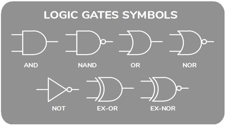
This is the list of all logic gates:
- AND Gate
- OR Gate
- NOT Gate
- NAND Gate
- NOR Gate
- EX-OR Gate
- EX-NOR Gate
Table of Contents
Implementation of Logic Gates using PLC Program
1. AND Gate
AND logic gate is the basic multiplication logic gate. The output will turn ON only if all the inputs will be ON.

The below figure shows the PLC ladder logic of AND gate, which shows the output coil turns “ON” when both the input will be ON.

2. OR Gate
OR logic gate is the basic addition logic gate. The output will turn ON if any of the inputs will be ON.
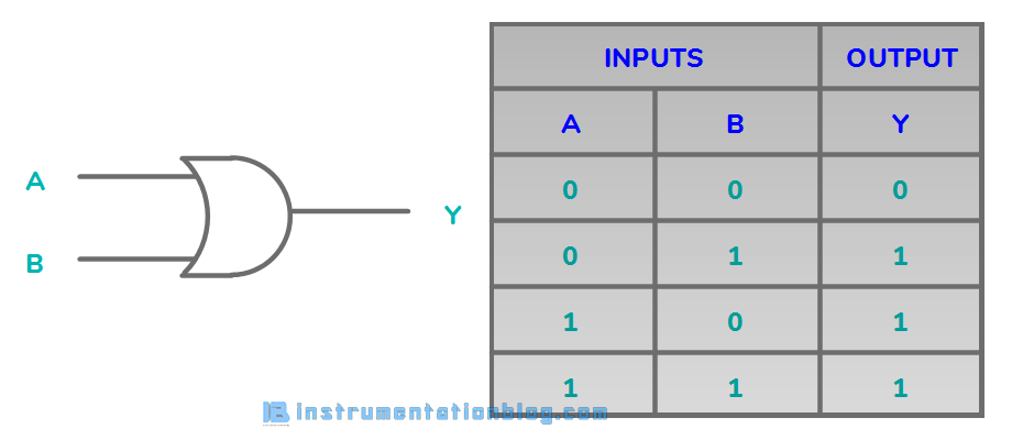
The below figure shows the PLC ladder logic of the OR gate, which shows the output coil turns “ON” when any one of the inputs will be ON.

3. NOT Gate
NOT logic gate is the inverse logic gate. When the input is ON, the output will be OFF and when the input is OFF, the output will be ON.
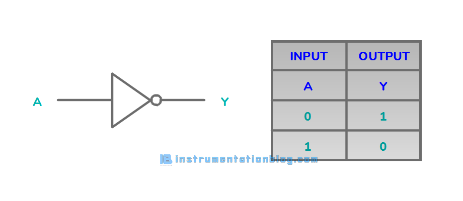
The below figure shows the PLC ladder logic conversion of NOT gate, which shows the output works exactly opposite of the input.

4. NAND Gate
NAND logic gate is the combination of AND and NOT logic gates, Output will only be OFF when all the inputs will be ON.
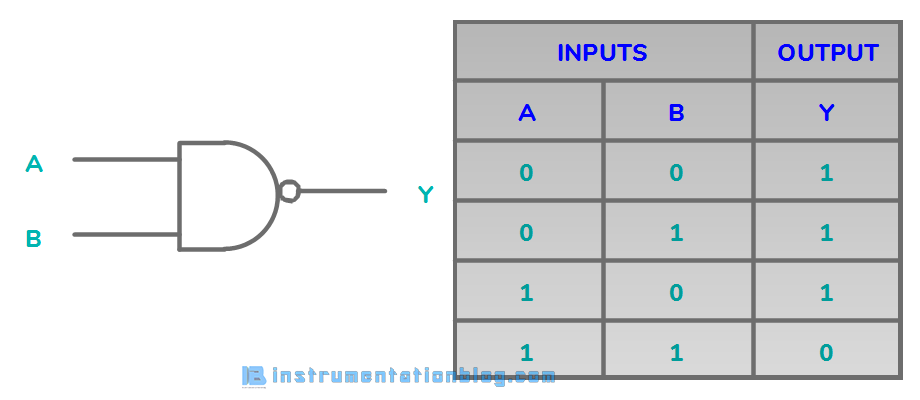
The below figure shows the plc ladder logic conversion of the NAND gate, which shows that when all the inputs will ON then the output will be OFF.
5. NOR Gate
NOR logic gate is the combination of OR and NOT logic gates, Output will only be ON when all the inputs will be OFF.
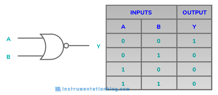
The below figure shows the PLC ladder logic of the NOR logic gate, which shows that Output will only turn ON when all the inputs will be OFF.
6. EX-OR Gate
EX-OR logic gate is the combination of AND, NOT and OR gate.
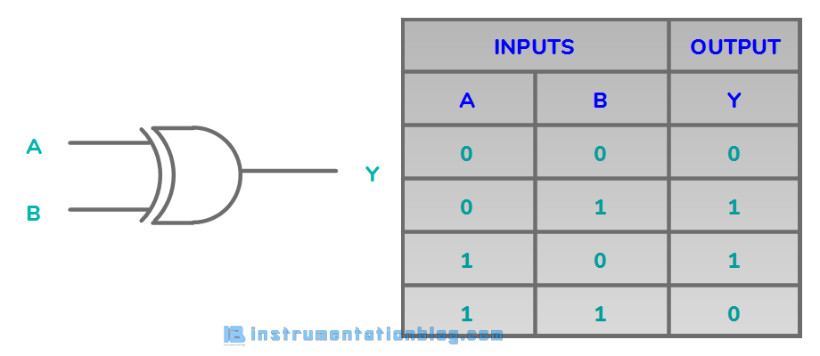
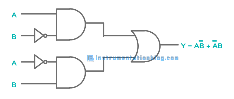
The below figure shows the ladder logic conversion of the EX-OR logic gate.
7. EX-NOR Gate
EX-NOR logic gate is the combination of AND, OR and NOT gate.
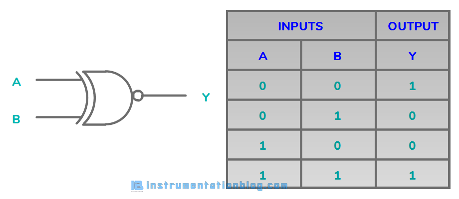
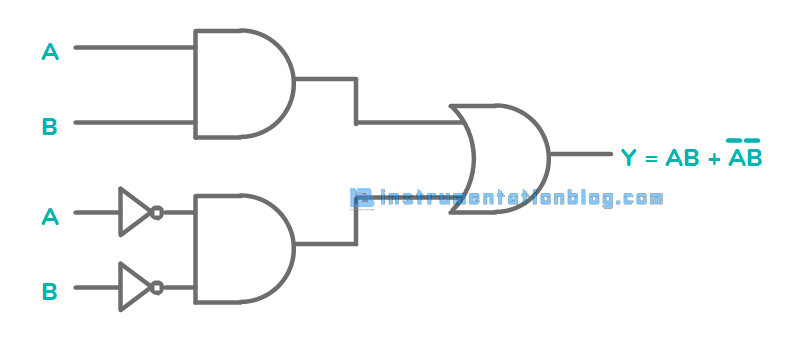
The below figure shows the ladder logic conversion of the EX-NOR logic gate.
Thanks